Do you have a question about the Aiwa NSX-R30EZ and is the answer not in the manual?
Technical details for the main unit's tuner, amplifier, and deck sections.
Technical details for the front speaker system, including units and impedance.
Warnings and cautions regarding laser exposure during servicing operations.
Procedures to follow before replacing the optical block to prevent damage.
Procedure to safely discharge electrolytic capacitors in the power supply block.
Initial checks to perform before replacing the microcomputer.
Steps to perform a forced reset on the microcomputer for troubleshooting.
Verifying the microcomputer's soldering for potential connectivity issues.
Explanation of the coding system for chip resistors.
Visual guide to identifying various transistor types.
Diagram showing the wiring connections for the main circuit board.
First part of the main circuit schematic diagram.
Second part of the main circuit schematic diagram.
Diagram illustrating wiring connections on the front circuit board.
Schematic diagram for the front and deck sections.
Wiring diagram for the power transformer (PT) circuit board.
Schematic diagram for the power transformer (PT) circuit.
Wiring diagram for the headphone (HP) circuit board.
Schematic diagram for the headphone (HP) circuit.
Wiring diagram for the deck and head circuit boards.
Grid assignment details for the front panel display.
Anode connection details for the front panel display.
Block diagram for the BU3881FV integrated circuit.
Block diagram for the LA1845N-A integrated circuit.
Block diagram for the LC721310-N integrated circuit.
Block diagram for the BU1920FS integrated circuit.
Detailed description of pins for the µPD780226GF/780228GF IC, covering pages 34 and 35.
Locations of test points and components for tuning adjustments on the main board.
Adjustment points for the deck circuit board.
Adjustment points for the headphone circuit board.
Procedure for adjusting LW voltage and tuning for optimal reception.
Procedure for checking MW voltage and tuning.
Procedure for adjusting and checking FM voltage and tuning.
Procedure for checking and adjusting the unit's clock frequency.
Procedures for adjusting MW Intermediate Frequency and tracking.
Procedure for adjusting LW tracking.
Checking the MW auto-stop function for proper operation.
Adjustments for FM tracking, separation, and auto-stop features.
Procedure for adjusting tape speed on Deck 2 using a test tape.
Adjusting tape head azimuth for optimal playback on both decks.
Checking the playback frequency response for both decks.
Verifying playback sensitivity for both tape decks.
Adjusting record/playback frequency for Deck 2.
Checking playback sensitivity for Deck 2.
Procedure for adjusting the clock frequency on the front panel.
Instructions on how to enter the CD test mode using buttons and power.
Methods for safely exiting the CD test mode.
Description of functions and checks available in CD test mode.
Instructions for removing speaker units based on different physical types.
Steps for removing and attaching the front speaker panel.
| Brand | Aiwa |
|---|---|
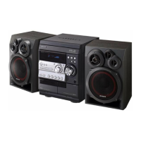
| Model | NSX-R30EZ |
| Category | Stereo System |
| Language | English |