EasyManua.ls Logo

Aiwa NSX-R20 Service Manual

Aiwa NSX-R20
56 pages
To Next Page IconTo Next Page
Page #1 background imageLoading...
Page #1 background image
SERVICE MANUAL
DATA
CD STEREO SYSTEM
NSX-D20
NSX-R20
S/M Code No. 09-024-454-0R1
REVISION
U(S)
LH(S)
BASIC CD MECHANISM : BZG-2 ZD9GNC1
BASIC TAPE MECHANISM : CMAT6Z2(1+1)ALPS
This Service Manual is the "Revision Publishing" and replaces "Simple Manual"
(S/M Code No. 09-01C-454-0T1).
• If requiring information about the CD mechanism, see Service Manual of
BZG-2, (S/M Code No. 09-023-353-2N8).
NSX–D20
SPEAKERSYSTEM
CD
CASSEIVER
SX–ND20CX–ND20
REMOTE
CONTROLLER
RC–CAS03(VS)
NSX–R20 SX–NR20CX–NR20
w
w
w
.
x
i
a
o
y
u
1
6
3
.
c
o
m
Q
Q
3
7
6
3
1
5
1
5
0
9
9
2
8
9
4
2
9
8
T
E
L
1
3
9
4
2
2
9
6
5
1
3
9
9
2
8
9
4
2
9
8
0
5
1
5
1
3
6
7
3
Q
Q
TEL 13942296513 QQ 376315150 892498299
http://www.xiaoyu163.com
Question and Answer IconNeed help?

Do you have a question about the Aiwa NSX-R20 and is the answer not in the manual?

Aiwa NSX-R20 Specifications

General IconGeneral
BrandAiwa
ModelNSX-R20
CategoryStereo System
LanguageEnglish

Summary

SPECIFICATIONS

Main Unit Specifications

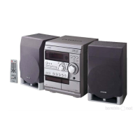
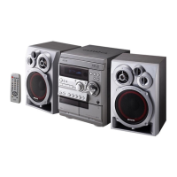
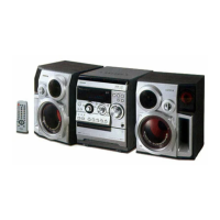
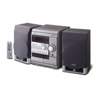
Details for the main unit including tuner, amplifier, CD player, and cassette deck.

Front Speaker Specifications

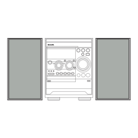
Details for the front speakers including system, impedance, dimensions, and weight.

SERVICE SAFETY AND PRECAUTIONS

Laser Safety Precautions

Cautions against direct eye exposure to the laser beam during servicing.

Pre-Repair Procedures

Steps for capacitor discharge and microcomputer verification before repair.

ELECTRICAL PARTS LIST

CIRCUIT DIAGRAMS AND WIRING

Main Unit Diagrams

Wiring and schematic diagrams for the main unit and headphone output.

Front Unit Diagrams

Wiring and schematic diagrams for the front unit.

PT Unit Diagrams

Wiring and schematic diagrams for the PT unit.

Deck Unit Wiring

Wiring diagram for the deck mechanism.

INTEGRATED CIRCUIT (IC) DETAILS

IC Block Diagrams

Functional blocks and pin assignments for key ICs used in the unit.

IC Description: µPD780226GF-033-3BA

Detailed pin function descriptions for the µPD780226GF-033-3BA IC.

FL DISPLAY INTERFACE

FL Display Pinout and Connections

Grid, anode, and pin connection details for the FL display.

ADJUSTMENT PROCEDURES

Tuner Adjustments

Procedures for AM, FM, and Clock tuning adjustments.

Deck Adjustments

Procedures for tape speed, wow/flutter, azimuth, and frequency response adjustments.

Front Panel Clock Adjustment

Procedure for clock adjustment specific to the front panel.

CD TEST MODE

Starting and Exiting CD Test Mode

Steps to enter and exit the CD test mode.

CD Test Mode Functions

Details on various modes and their functions within the test mode.

MECHANICAL SECTIONS

Mechanical Exploded View

Diagram showing the assembly breakdown of mechanical parts.

Mechanical Parts List

List of all mechanical components and their part numbers.

TAPE MECHANISM SECTIONS

Tape Mechanism Exploded View

Diagram showing the assembly breakdown of the tape mechanism.

Tape Mechanism Parts List

List of all tape mechanism components and their part numbers.

SPEAKER SECTIONS

Speaker Disassembly Instructions

Steps for safely disassembling the speaker units.

Speaker Parts List (SX-NR20 / ND20)

List of speaker components and their part numbers.

ACCESSORIES & OTHER PARTS

Accessories Parts List

List of included accessories and their part numbers.

Other Parts List (CX-ND20 / NR20)

List of miscellaneous parts not covered elsewhere.

COLOR NAME TABLE

Related product manuals