Do you have a question about the Aiwa NSX-SZ22 and is the answer not in the manual?
Detailed specifications for the FM tuner section.
Detailed specifications for the MW tuner section.
Detailed specifications for the LW tuner section.
Specifications related to the amplifier output, distortion, and impedance.
Specifications for the cassette deck's track format, frequency response, and heads.
Specifications for the CD player's laser, DAC, and signal-to-noise ratio.
Specifications for speaker units, impedance, and dimensions.
General specifications including power requirements and unit dimensions.
Critical safety warnings regarding laser beam exposure during servicing.
General cautions, attention notices, and optical block replacement steps.
Procedure to safely discharge power supply electrolytic capacitors before repair.
Steps to check and reset the microcomputer, including soldering verification.
Comprehensive list of electrical components including ICs, transistors, diodes, and capacitors.
Explanation of the coding system used for chip resistors.
Diagrams showing the pin configurations of various transistors.
Diagrams for FL display grid assignment and anode connections.
Diagram showing the physical placement of components on the main circuit board.
Schematics for the amplifier and tuner sections of the main circuit board.
Schematic diagram for the front circuit board.
Diagrams for the PT board's PCB layout and schematic.
Diagram showing the PCB layout for the tape deck mechanism.
Visual representation of the internal structure and functions of key ICs.
Detailed explanation of pin functions for the µPD780226GF microcontroller and others.
Step-by-step guide for adjusting the tuner section parameters.
Step-by-step guide for adjusting the tape deck section parameters.
Procedure for adjusting the microcomputer's oscillator frequency.
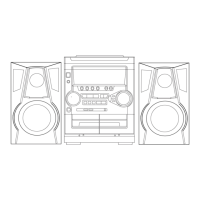
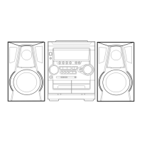
Diagram showing the exploded view of the entire unit and its main parts.
List of mechanical parts with reference numbers, part numbers, and descriptions.
Table mapping color symbols to their corresponding colors.
Diagram showing the exploded view of the tape mechanism components.
List of parts for the tape mechanism with reference numbers and descriptions.
Instructions for disassembling speaker units using different methods.
Step-by-step guide for removing and attaching the speaker's front panel.
List of parts specific to the speaker units.
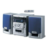
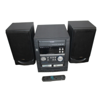
List of included accessories and package contents.
| Brand | Aiwa |
|---|---|
| Model | NSX-SZ22 |
| Category | Stereo System |
| Language | English |