EasyManua.ls Logo

Aiwa NSX-SZ50 Service Manual

Aiwa NSX-SZ50
35 pages
To Next Page IconTo Next Page
Page #1 background imageLoading...
Page #1 background image
SERVICE MANUAL
DATA
COMPACT DISC STEREO
SYSTEM
BASIC TAPE MECHANISM : 6ZM-3 PR2NM
BASIC CD MECHANISM : AZG-1 ZA3RDM
NSX-SZ50
NSX-SZ52
EZ, K
EZ
S/M Code No. 09-004-424-6R2
REVISION
This Service Manual is the "Revision Publishing" and replaces "Simple Manual",
(S/M Code No. 09-002-424-6T2).
If requiring information about the CD mechanism, see Service Manual
of AZG-1, (S/M Code No. 09-001-335-3NC).
NSX-SZ50
SPEAKER
SYSTEM
CD
CASSEIVER
REMOTE
CONTROLLER
NSX-SZ52
CX-NSZ50 SX-WNSZ50
CX-NSZ52
SX-WNSZ52
RC-ZAS01
RC-ZAS01
All manuals and user guides at all-guides.com
all-guides.com
Question and Answer IconNeed help?

Do you have a question about the Aiwa NSX-SZ50 and is the answer not in the manual?

Aiwa NSX-SZ50 Specifications

General IconGeneral
BrandAiwa
ModelNSX-SZ50
CategoryStereo System
LanguageEnglish

Summary

Service Manual Overview

Model Identification

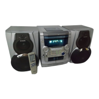
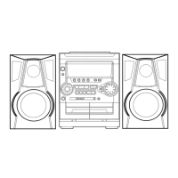
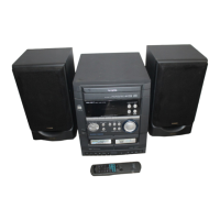
Identifies the AIWA NSX-SZ50 and NSX-SZ52 models covered in the service manual.

Specifications

Main Unit Specifications

Technical parameters for the main unit including tuner, amplifier, and cassette/CD sections.

Speaker System Specifications

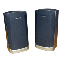
Technical parameters for the SX-WNSZ50/SX-WNSZ52 speaker systems.

Laser Safety Precautions

Optical Block Handling Safety

Precautions for safe handling and replacement of the optical block, including ESD.

Pre-Repair Procedures

Electrolytic Capacitor Discharge

Step-by-step guide to safely discharge power supply capacitors before servicing.

Microcomputer Diagnostic Checks

Initial checks and considerations before replacing the microcomputer unit.

Microcomputer Procedures

Microcomputer Reset Procedure

Method for performing a forced reset on the microcomputer.

Microcomputer Soldering Inspection

Procedure to check the microcomputer's soldering quality.

Electrical Parts List - Core Components

Electrical Parts List - Capacitors

Electrical Parts List - Miscellaneous

Electrical Parts List - Connectors & Switches

Component Identification

Transistor Illustrations

Visual diagrams showing transistor pinouts and types.

Chip Resistor Coding

Explanation of the coding system for chip resistors.

Display Grid Assignment

Anode Connection Table

Schematic Diagram - Amplifier and Head Sections

Schematic Diagram - Tuner Section

Schematic Diagram - Front and Deck Sections

PT Board Wiring Diagram

Schematic Diagram - Power Transformer Section

Deck and Head Wiring Diagram

Deck 2 Wiring Diagram

IC Block Diagrams

IC Block Diagrams (Continued)

IC Block Diagrams (Further)

IC Descriptions

IC Descriptions (Continued)

Adjustment Procedures

Tuner Section Adjustments

Procedures for calibrating tuner section parameters like frequency and VT.

Deck Section Adjustments

Procedures for calibrating tape speed, azimuth, and frequency response.

Front Section Adjustment

Procedure for adjusting the front section's oscillator frequency.

Mechanical Exploded View

Mechanical Parts List

Tape Mechanism Exploded View

Tape Mechanism Parts List

Speaker Disassembly Instructions

Front Panel Removal Guide

Detailed instructions for removing the speaker's front panel using specific tools.

Speaker Parts List

Accessories and Package List

Related product manuals