EasyManua.ls Logo

Aiwa NSX-SZ80 User Manual

Aiwa NSX-SZ80
47 pages
To Next Page IconTo Next Page
Page #1 background imageLoading...
Page #1 background image
SERVICE MANUAL
DATA
COMPACT DISC STEREO
CASSETTE RECEIVER
BASIC TAPE MECHANISM : 2ZM-3MK2 PR7NM
BASIC CD MECHANISM : AZG-1 ZD3RNDM
NSX-SZ80
NSX-SZ83
NSX-AJ80
NSX-SZ80E
LH
LH
U
HA
S/M Code No. 09-003-424-4R1
REVISION
This Service Manual is the "Revision Publishing" and replaces "Simple Manual"
NSX-SZ80/SZ83/AJ80/SZ80E (LH, U, HA), (S/M Code No. 09-001-424-4T1).
If requiring information about the CD mechanism, see Service Manual of
AZG-1 ZD3RNDM, (S/M Code No. 09-001-335-3N8).
NSX–SZ80 (LH)
MAIN
SPEAKER
SYSTEM
CD
CASSEIVER
SX–WNH83CX–NSZ83
REMOTE
CONTROLLER
NSX–SZ83 (LH)
RC–ZAS01
NSX–AJ80 (U)
NSX–SZ80E (HA)
CX–NSZ80
CX–NAJ80
CX–NSZ80E
SX–WNSZ80
SX–WNAJ85
SX–WNSZ80
SATELLITE
SPEAKER
SX–S80
All manuals and user guides at all-guides.com
all-guides.com
Question and Answer IconNeed help?

Do you have a question about the Aiwa NSX-SZ80 and is the answer not in the manual?

Aiwa NSX-SZ80 Specifications

General IconGeneral
CD PlayerYes
Radio TunerAM/FM
Speakers2
Tuner BandsAM/FM
TypeStereo System
Cassette DeckDual Cassette Deck
Tape DeckDual Cassette

Summary

Service Manual Introduction and Specifications

System Overview and Detailed Specifications

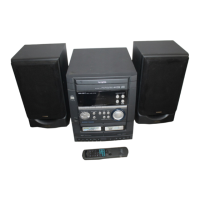
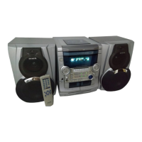
Introduces the service manual and provides a high-level overview of system specifications and models.

Safety and Repair Procedures

Laser Safety and Servicing Precautions

Emphasizes laser safety during servicing and optical block replacement.

Pre-Repair Checks and Microcomputer Troubleshooting

Capacitor Discharge, Pre-Checks, and Reset

Details capacitor discharge, microcomputer pre-checks, and reset procedures.

Component Lists and Identification

Electrical Main Parts List

Lists key electrical components like ICs, transistors, and diodes.

Transistor Illustrations and Chip Resistor Coding

Shows transistor diagrams and chip resistor coding system.

Circuit Diagrams and Wiring

Wiring Diagrams (Main, VM, Front, Deck)

Illustrates wiring connections for main, VM, front, CD key, microphone, and deck boards.

Schematic Diagrams (Amplifier, Tuner, CD Deck)

Detailed schematics for amplifier, VM, tuner, and cassette deck sections.

Power Transformer Schematics and Wiring

Wiring and schematics for power transformers (U, LH, HA models).

Front Panel Display (FL) Information

Details FL display grid layout and anode connection mapping.

Integrated Circuit (IC) Block Diagrams

Shows block diagrams and pin functions for various ICs.

Adjustment Procedures

Tuner, Deck, Front, and Transformer Adjustments

Identifies adjustment points and provides procedures for tuner, deck, front, and transformer sections.

Mechanical Information

Exploded Views and Part Lists

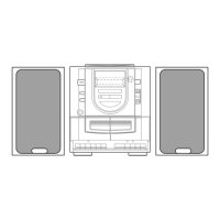
Provides mechanical exploded views and part lists for the unit and tape mechanism.

Speaker Information

Disassembly, Reassembly, and Parts Lists

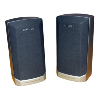
Guides for speaker disassembly, reassembly, and parts lists for different models.

Accessories and Package Contents

Included Items List

Lists the accessories and package contents provided with the unit.

Related product manuals