Do you have a question about the Aiwa NSX-SZ700 and is the answer not in the manual?
Details tuning range and sensitivity for FM and AM tuners.
Covers power output, distortion, inputs, outputs, and CD/Cassette player specs.
Lists speaker system details and general unit specifications like power and dimensions.
Critical warnings and cautions regarding laser beam exposure during servicing operations.
Precautions for replacing the optical block, including static discharge management.
Procedure for safely discharging electrolytic capacitors before starting repairs.
Essential checks for the microcomputer and its HOLD terminal before replacement.
List of integrated circuits (ICs) with reference, part numbers, and descriptions.
List of transistors with reference, part numbers, and descriptions.
Lists diodes and capacitors on the Main Circuit Board (C.B.).
Continues the list of capacitors, detailing part numbers and descriptions.
Lists various connectors and cables with their part details.
Lists components located on the Front Circuit Board (C.B.).
Continues the list of components on the Front Circuit Board (C.B.).
Lists components on the Power Transformer (PT) Circuit Board (C.B.).
Lists parts for terminals, switches, and operation panels (M-OP, S-OP, MOTOR).
Explains the coding system for chip resistors and their corresponding values.
Provides illustrations and pinouts for various Bipolar Junction Transistors (BJTs).
Provides illustrations and pinouts for various Field-Effect Transistors (FETs).
Diagram showing the wiring connections for the Main Circuit Board.
Diagram showing the wiring connections for the Power Transformer Circuit Board.
Detailed schematic of the amplifier section, including various circuits and components.
Detailed schematic of the tuner section, showing radio frequency circuits.
Schematic diagram illustrating the power transformer connections for the U model.
Diagram showing wiring for the Front Circuit Board (U model).
Diagrams for Motor Circuit Board and G BOX SW Circuit Board wiring.
Diagram showing wiring for the Main Operation Panel Circuit Board.
Diagram showing wiring for the Sub Operation Panel Circuit Board.
Schematics for Front, Motor, M-OP, S-OP, G BOX SW, and Deck Circuit Boards (U model).
Schematics for Front, Motor, M-OP, S-OP, and Deck Circuit Boards (LH model).
Diagram showing wiring for the Power Transformer Circuit Board (LH model).
Schematic diagram illustrating the power transformer connections for the LH model.
Diagrams showing wiring for the Deck, Head-1, and Head-2 Circuit Boards (LH model).
Diagram showing wiring for the Deck Circuit Board (U model).
Table detailing the grid assignment and anode connection for the FL display.
Block diagrams illustrating the internal functions of key ICs.
Detailed description of pins 1 through 29 for the LC866560W-5V01 IC.
Detailed description of pins 30 through 55 for the LC866560W-5V01 IC.
Details pins 56 through 72 of the LC866560W-5V01 IC, including I/O and function.
Details pins 73 through 96 of the LC866560W-5V01 IC, including I/O and function.
Details pins 97 through 100 of the LC866560W-5V01 IC, including I/O and function.
Procedures for adjusting clock frequency, AM/FM VT, AM/FM tracking, and AM IF.
Procedures for adjusting tape speed, head azimuth, and frequency response.
Procedure for adjusting the microcomputer (µ-CON) OSC frequency.
Instructions on how to start and exit the CD Test Mode.
Describes functions and checking items for each mode within the CD Test Mode.
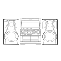
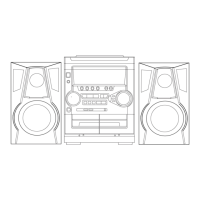
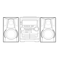
Exploded view of the main unit, showing the arrangement of various mechanical parts.
Detailed list of mechanical parts for the main unit, including part numbers.
Table mapping color symbols to their respective color names.
Exploded view illustrating the mechanical components of the tape mechanism for the U model.
Detailed list of mechanical parts for the tape mechanism (U model).
Exploded view illustrating the mechanical components of the tape mechanism for the LH model.
Detailed list of mechanical parts for the tape mechanism (LH model).
Provides three types of instructions for disassembling speaker units.
Instructions on how to attach the Front Panel (PANEL, FR) to the speaker.
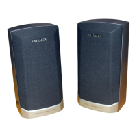
Lists parts specific to SX-NAJ702, SX-NSZ705, and SX-WNSZ703 speaker systems.
Lists accessories and package contents, including antennas and manuals.
| Type | Mini Hi-Fi System |
|---|---|
| CD Player | Yes |
| Radio Tuner | FM/AM |
| Bluetooth | No |
| USB Port | No |
| Number of Discs | 3 |
| Remote Control | Yes |
| Speakers (2) | Yes |
| Cassette Deck | Dual |
| Tape Deck | Dual |
| Speakers | 2 |