Do you have a question about the Aiwa NSX-SZ52 and is the answer not in the manual?
Details specifications for FM, MW, LW tuners and the cassette deck.
Covers specifications for the amplifier section and the compact disc player.
Lists specifications for the speaker system and general unit information.
Provides essential warnings and cautions regarding laser beam exposure during servicing.
Details precautions for handling and replacing the optical pickup block.
Procedure for safely discharging power supply electrolytic capacitors before repair.
Steps to check the microcomputer before replacement, including HOLD terminal status.
Lists part numbers and descriptions for integrated circuits and transistors.
Enumerates capacitors used on the Main Circuit Board (C.B).
Visual representations of various transistor package types and pinouts.
Explains the part coding system for chip resistors.
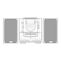
Shows the grid layout for front panel controls and indicators.
Details the anode connections for the display segments.
Wiring diagram and component placement for the main circuit board.
Schematic diagram for the function and amplifier sections of the main C.B.
Schematic diagram for the tuner section of the main circuit board.
Illustrates the wiring connections for the front circuit board.
Detailed schematic of the front circuit board.
Detailed schematic of the deck circuit board.
Wiring diagram for the power supply (PT) circuit board.
Schematic diagram illustrating the power supply (PT) circuit board components.
Wiring diagram for the deck circuit board.
Wiring diagram for the head unit circuit board.
Pinout details for the Deck 2 connector (CON351).
Block diagrams illustrating the internal functions of ICs LA1843 and LC72131D.
Block diagrams for ICs BA3835S and BU2092F.
Block diagrams for ICs M61503FP and BU1920FS.
Detailed pin descriptions for the LC866548V and LC866560W integrated circuits.
Procedures for adjusting the tuner section, including frequency and tracking.
Procedures for adjusting tape speed, azimuth, and frequency response.
Procedure for adjusting the microcomputer oscillator frequency.
Exploded view diagram showing the assembly of the main unit.
Comprehensive list of mechanical parts for the main unit.
Exploded view illustrating the assembly of the tape mechanism.
Detailed list of parts for the tape mechanism.
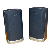
Step-by-step instructions for disassembling speaker units.
Guide on how to remove and attach the speaker front panel.
List of individual parts comprising the speaker units.
Lists included accessories and packaging components.
| CD Player | Yes |
|---|---|
| Radio Tuner | Yes |
| Cassette Deck | Yes |
| Bluetooth | No |
| Functions | CD, Radio, Cassette |
| Remote Control | Yes |
| Weight | 5.5 kg |
| Cassette Deck Type | Single |
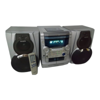
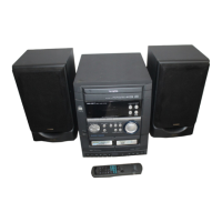
| Type | Mini Hi-Fi System |
| CD Player Type | Single |