EasyManua.ls Logo

Aiwa NSX-SZ73 User Manual

Aiwa NSX-SZ73
37 pages
To Next Page IconTo Next Page
Page #1 background imageLoading...
Page #1 background image
SERVICE MANUAL
DATA
COMPACT DISC STEREO
CASSETTE RECEIVER
NSX-SZ70
NSX-SZ72
NSX-SZ73
EZ,K
EZ
EZ
S/M Code No. 09-006-425-3R3
REVISION
BASIC TAPE MECHANISM: 2ZM-3MK2 PR4NM
BASIC CD MECHANISM: AZG-1 ZD3RDM
This Service Manual is the “Revision Publishing” and replaces “Simple Manual”
NSX-SZ70/SZ72/SZ73 (S/M Code No. 09-002-425-3T3).
If requiring information about the CD mechanisim, see Service Manual of AZG-1
(S/M Code No. 09-001-335-3N8).
CD-CASSEIVER
CX-NSZ70
CX-NSZ72
CX-NSZ73
SPEAKER
SX-WNSZ70
SX-WNSZ71
SX-WNH81
SYSTEM
NSX-SZ70
NSX-SZ72
NSX-SZ73
REMOTE CONTROLLER
RC-ZAS01
All manuals and user guides at all-guides.com
all-guides.com
Question and Answer IconNeed help?

Do you have a question about the Aiwa NSX-SZ73 and is the answer not in the manual?

Aiwa NSX-SZ73 Specifications

General IconGeneral
TypeStereo Receiver
Power Output100W per channel (RMS)
TunerAM/FM
Number of Channels2
Speaker Impedance6 Ohms
InputsAux
Cassette DeckDual
Frequency Response20Hz - 20kHz

Summary

Aiwa Service Manual Overview

System Configuration and Component Mapping

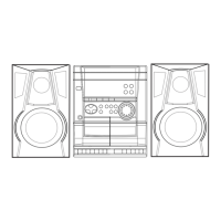
Details system models, basic mechanisms, and component mapping.

Manual Revision Information

Notes on manual revisions and replacement of previous versions.

Technical Specifications

Tuner, Amplifier, and CD Player Specifications

Technical details for tuner, amplifier, and compact disc player sections.

Speaker System and General Specifications

Specifications for speaker systems and overall unit parameters.

Laser Safety Precautions During Servicing

Laser Emission Warnings and Handling

Guidance on safe laser beam observation and handling procedures.

Optical Block Replacement Safety

Safety measures when replacing the optical pickup block.

Pre-Repair Procedures and Troubleshooting

Power Supply Capacitor Discharge Procedure

Steps to safely discharge power supply capacitors before repair.

Microcomputer Troubleshooting and Reset

Methods for checking microcomputer function and performing resets.

Circuit Diagrams

Main Unit Wiring Diagrams

Wiring connections for the main unit.

Main Unit Schematic Diagrams (Amplifier/VM)

Schematic for the main unit's amplifier and VM sections.

Adjustment Procedures

Tuner Section Adjustment Procedures

Procedures for adjusting tuner circuit parameters.

Deck Section Adjustment Procedures

Procedures for adjusting tape deck speed and frequency response.

Mechanical Information

Main Unit Exploded View

Visual breakdown of the main unit's mechanical components.

Speaker Unit Disassembly Instructions

Step-by-step guide for disassembling speaker units.

Related product manuals