Do you have a question about the Aiwa SX-WNSZ50 and is the answer not in the manual?
Power output, distortion, inputs, and speaker compatibility for the amplifier.
Track format, frequency response, recording system, and heads used.
Laser type, D-A converter, signal-to-noise ratio, and harmonic distortion.
Precautions for avoiding eye exposure to laser beams during servicing.
Warnings about potential hazardous radiation exposure from improper adjustments.
Steps to prevent electrostatic discharge damage to the laser diode.
Procedure to safely discharge electrolytic capacitors before repair.
Checks to perform before replacing the microcomputer.
Procedure for forced reset if the microcomputer is not functioning correctly.
Schematic diagram for the main board's function and amplifier sections.
Schematic diagram for the main board's tuner section.
Schematic diagram for the power transformer (PT) circuit board.
Detailed pinout and function descriptions for the LC866548V and LC866560W ICs.
Procedures for adjusting tuner frequency and tracking parameters.
Procedures for adjusting tape speed, head azimuth, and frequency response.
| Brand | Aiwa |
|---|---|
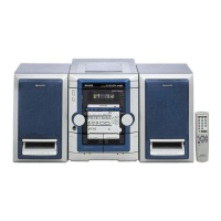
| Model | SX-WNSZ50 |
| Category | Stereo System |
| Language | English |