EasyManua.ls Logo

Aiwa SX-NBL25 User Manual

Aiwa SX-NBL25
41 pages
To Next Page IconTo Next Page
Page #1 background imageLoading...
Page #1 background image
SERVICE MANUAL
DATA
COMPACT DISC STEREO SYSTEM
BASIC TAPE MECHANISM : 6ZM-3 PR2NM
BASIC CD MECHANISM : AZG-1 VZD3RDM
NSX-VC38
HR, HS
S/M Code No. 09-006-430-3R1
REVISION
This Service Manual is the "Revision Publishing" and replaces "Simple Manual"
NSX-VC38 <HR> (S/M Code No. 09-004-430-3T1).
• If requiring information about the CD mechanism, see Service Manual of AZG-1,
(S/M Code No. 09-001-335-3NG).
NSX–VC38 RC–ZAS07
SYSTEM
CD
CASSEIVER
REMOTE
CONTROLLER
CX–NVC38
SPEAKER
SX–NBL25
All manuals and user guides at all-guides.com
all-guides.com
Question and Answer IconNeed help?

Do you have a question about the Aiwa SX-NBL25 and is the answer not in the manual?

Aiwa SX-NBL25 Specifications

General IconGeneral
BrandAiwa
ModelSX-NBL25
CategoryStereo System
LanguageEnglish

Summary

Specifications

Main Unit CX-NVC38 Specifications

Details on tuner, amplifier, and cassette deck sections of the main unit.

Compact Disc Player Section Specifications

Details on laser, D/A converter, signal-to-noise ratio, and audio data.

General Specifications

Power requirements, consumption, dimensions, and weight of the unit.

Speaker System SX-NBL25 Specifications

Impedance, sensitivity, dimensions, and weight of the speaker system.

Laser Beam Safety and Optical Block Precautions

Laser Beam Safety Warnings

Cautionary notes regarding laser exposure during servicing.

Optical Block Replacement Precautions

Guidelines for safe replacement of the optical block.

Pre-Repair Notes and Checks

Forced Discharge of Power Supply Capacitors

Procedure to safely discharge electrolytic capacitors before repair.

Microcomputer Pre-Exchange Checks

Steps to verify microcomputer functionality before replacement.

Electrical Main Parts List

Chip Resistor Part Code

Explanation of the coding system for chip resistors.

Transistor Illustrations

FL (HNA-10SS12) Grid Assignment / Anode Connection / Pin Connection

Grid Assignment

Layout of the grid segments for the display panel.

Anode Connection Table

Mapping of pins to anode connections for display segments.

Pin Connection Table

Detailed pinout and connection mapping for the display.

Main Board Wiring Diagram - 1

Main Board Wiring Diagram - 2 (HS)

Main Board Schematic Diagram - 1

Main Board Schematic Diagram - 2 (Deck Section)

Main Board Schematic Diagram - 3 (Tuner Section)

Main Board Schematic Diagram - 4 (Tuner Section HS)

Front Board Wiring Diagram

Front and Deck Schematic Diagram

Amplifier Board Wiring Diagram

Amplifier Board Schematic Diagram

Power Supply Board Wiring Diagram

Power Supply Board Schematic Diagram

Deck and Head Wiring Diagram

Integrated Circuit Block Diagrams

IC LA1843 Block Diagram

Functional overview of the LA1843 integrated circuit.

IC M65849BFP6310 Block Diagram

Functional overview of the M65849BFP6310 integrated circuit.

IC LC72131D Block Diagram

Functional overview of the LC72131D integrated circuit.

IC BA7762AFS Block Diagram

Functional overview of the BA7762AFS integrated circuit.

IC BD3876KS2 Block Diagram

IC μPD780226GF-017-3BA Pin Descriptions

IC LC72131D Pin Descriptions

Adjustment Procedures

Tuner Section Adjustments

Procedures for clock frequency, VT, tracking, and IF adjustments.

Deck Section Adjustments

Procedures for tape speed, azimuth, frequency response, and sensitivity.

General Performance Adjustments

DC balance, output level, and FM separation checks.

Microcomputer Oscillator Adjustment

Procedure for tuning the microcomputer oscillator frequency.

CD Test Mode Operations

Activating and Cancelling CD Test Mode

Steps to enter and exit the CD test mode.

CD Test Mode Functions

Description of available test modes and their operations.

CD Test Mode Operation Outline

Visual guide to the sequence of test modes.

Mechanical Exploded View

Mechanical Parts List

Color Name Table

Key for color coding used in parts identification.

Mechanical Exploded View (HS Model)

Mechanical Parts List (HS Model)

Color Name Table

Key for color coding used in parts identification.

Tape Mechanism Exploded View

Tape Mechanism Parts List

Speaker Disassembly and Reassembly

Speaker Unit Disassembly Types

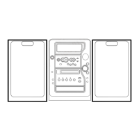
Instructions for disassembling speaker units (Types 1, 2, 3).

Front Panel Removal and Attachment

Procedures for removing and attaching the front panel.

Speaker Parts and Accessories

Speaker Component Parts List

List of parts specific to the speaker system.

Accessories and Package List

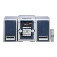
List of included accessories and package contents.

Related product manuals