EasyManua.ls Logo

Aiwa SX-NBL40 User Manual

Aiwa SX-NBL40
27 pages
To Next Page IconTo Next Page
Page #1 background imageLoading...
Page #1 background image
SERVICE MANUAL
DATA
NSX–BL44
(G)
RC–ZAS01
SYSTEM
CD
CASSEIVER
REMOTE
CONTROLLER
CX–NBL44
COMPACT DISC
STEREO SYSTEM
BASIC TAPE MECHANISM : 6ZM-3 PR2NM(44/46)
BASIC TAPE MECHANISM : 6ZM-3 YPR2N(DR6)
BASIC CD MECHANISM : AZG-1 ZA3RDM(44/46)
BASIC CD MECHANISM : AZG-1 YZA3RDM(DR6)
NSX-BL44
NSX-BL46
NSX-DR6
EZ,K,G
EZ
EZ
S/M Code No. 09-002-429-5N2
If requiring information about the CD mechanism, see Service Manual of AZG-1
(S/M Code No. 09-001-335-3NC).
SPEAKER
SX-NSZ53
NSX–BL44
(EZ/K)
CX–NBL44 SX–NBL40
NSX–BL46
(EZ)
NSX–DR6
(EZ)
CX–NDR6 SX–NBL40
CX–NBL46 SX–NBL42
All manuals and user guides at all-guides.com
all-guides.com
Question and Answer IconNeed help?

Do you have a question about the Aiwa SX-NBL40 and is the answer not in the manual?

Aiwa SX-NBL40 Specifications

General IconGeneral
ManufacturerAiwa
CD PlayerYes
USB PlaybackYes
FM TunerYes
BluetoothYes
AUX InputYes
Remote ControlYes
Power Output40W

Summary

SERVICE MANUAL INTRODUCTION

Aiwa NSX Series Service Manual

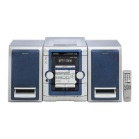
Overview and model identification for the service manual.

SYSTEM SPECIFICATIONS

Main Unit and Component Specs

Detailed specifications for main unit, cassette, CD player, and speakers.

LASER SAFETY PROTOCOLS

Eye Protection During Laser Servicing

Critical safety instructions for handling laser components during maintenance.

REPAIR PREPARATION AND NOTES

Pre-Repair Capacitor Discharge

Procedure for safely discharging power supply capacitors before repair.

REPAIR PREPARATION AND NOTES (Continued)

Microcomputer Troubleshooting and Reset

Steps for checking, resetting, and confirming microcomputer functionality.

ELECTRICAL PARTS LISTING

WIRING AND SCHEMATIC DIAGRAMS

WIRING AND SCHEMATIC DIAGRAMS

Function/Amplifier Section Schematic

Schematic diagram detailing the unit's function and amplifier circuits.

INTEGRATED CIRCUIT (IC) ANALYSIS

INTEGRATED CIRCUIT (IC) ANALYSIS

ADJUSTMENT PROCEDURES

Tuner Section Adjustments

Step-by-step guide for calibrating tuner frequencies and signal levels.

Deck Section Adjustments

Procedures for setting tape speed, head azimuth, and frequency response.

MECHANICAL ASSEMBLY VIEWS

MECHANISM PARTS LISTS

MECHANISM ASSEMBLY VIEWS

SPEAKER SYSTEM MAINTENANCE

Related product manuals