EasyManua.ls Logo

Aiwa SX-NSZ20 User Manual

Aiwa SX-NSZ20
28 pages
To Next Page IconTo Next Page
Page #1 background imageLoading...
Page #1 background image
SERVICE MANUAL
DATA
COMPACT DISC
STEREO SYSTEM
BASIC TAPE MECHANISM : ZZM-3
BASIC CD MECHANISM : AZG-1
NSX-AJ20
NSX-SZ20
NSX-SZ22
NSX-SZ27
NSX-DR1
U
LH,EZ,K,V
EZ
EZ
EZ
S/M Code No. 09-00C-423-4S3
SUPPLEMENT
• This Service Manual contains information about the difference between
NSX-AJ20/SZ20/SZ22/SZ27/DR1 (VA model) and NSX-AJ20/SZ20/
SZ22/SZ27/DR1. If requiring the other information, see Service Manual
as listed on page 2.
• Refer to MAIN C.B parts number for difference of model.
8A-NF9-701-010 is for NSX-AJ20<U>/SZ20<LH,EZ,K,V>/SZ22<EZ>/
SZ27<EZ>/DR1<EZ> VA model.
• If requiring information about the CD mechanism, see Service Manual
of AZG-1 (S/M Code No. 09-001-335-3N8)
NSX-AJ20<U>
SPEAKER
SYSTEM
CD
CASSEIVER
REMOTE
CONTROLLER
CX-NAJ20
SX-NAJ22
TAPE
MECHANISM
CD
MECHANISM
NSX-SZ20<LH>
NSX-SZ20
<EZ,K,V>
NSX-SZ22<EZ>
NSX-SZ27<EZ>
CX-NSZ20
ZZM-3 PR1NF
AZG-1 YKZD3RDF
SX-NSZ22
CX-NSZ20
RC-ZAS02
ZZM-3 PR1NM
AZG-1 ZD3RDM
SX-NSZ20
NSX-DR1<EZ>
CX-NSZ22
CX-NSZ27
CX-NDR1
SX-NSZ22
SX-NSZ20
RC-ZAS17
SX-NSZ20
w
w
w
.
x
i
a
o
y
u
1
6
3
.
c
o
m
Q
Q
3
7
6
3
1
5
1
5
0
9
9
2
8
9
4
2
9
8
T
E
L
1
3
9
4
2
2
9
6
5
1
3
9
9
2
8
9
4
2
9
8
0
5
1
5
1
3
6
7
3
Q
Q
TEL 13942296513 QQ 376315150 892498299
http://www.xiaoyu163.com
Question and Answer IconNeed help?

Do you have a question about the Aiwa SX-NSZ20 and is the answer not in the manual?

Aiwa SX-NSZ20 Specifications

General IconGeneral
Tuner BandsFM
CD PlayerYes
Remote ControlYes
FM RadioYes
AUX InputYes
TypeMini System
Power Output20W

Summary

Technical Specifications

Audio and Speaker Specifications

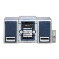
Specifications for Amplifier, CD Player, and Speaker systems, covering output, distortion, and impedance.

Electrical Main Parts List

Electrical Main Parts List - Capacitors

Schematic Diagrams: Main Circuit Boards

Main C.B 1 Diagram (U, LH, V)

Schematic for the main circuit board, covering AMP section for U, LH, V models.

Schematic Diagrams: Main Circuit Board 2

Main C.B 2 Diagram (EZ, K)

Schematic for the main circuit board, covering TUNER section for EZ, K models.

Schematic Diagrams: Amplifier Section

Amplifier Section Schematic

Detailed schematic of the amplifier section (Main 1/2).

Schematic Diagrams: Tuner Section (ULH)

Tuner Section Schematic (ULH)

Detailed schematic of the tuner section for ULH models (Main 2/2).

Schematic Diagrams: Tuner Section (EZ,K)

Tuner Section Schematic (EZ,K)

Detailed schematic of the tuner section for EZ,K models (Main 2/2).

Schematic Diagrams: Tuner Section (V)

Tuner Section Schematic (V)

Detailed schematic of the tuner section for V models (Main 2/2).

Front Section Diagrams

Front Wiring Diagram

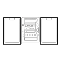
Illustrates the wiring connections for the front section of the unit.

Front PCB Schematic Diagram

Front PCB Schematic Diagram

Shows the schematic diagram of the front PCB, detailing its internal circuitry.

Power Transformer Diagrams (LH Model)

Power Transformer Schematic (LH Model)

Power Transformer Diagrams (U, EZ, K, V Models)

Power Transformer Schematic (U, EZ, K, V Models)

Adjustment Procedures

Tuner Section Adjustment Procedures

Detailed adjustment procedures for the tuner section, including frequency and VT checks.

Deck Section Adjustment Procedures

Detailed adjustment procedures for the deck section, covering tape speed and frequency response.

Mechanical Parts List and Color Table

Tape Mechanism Details

Tape Mechanism Parts List

Related product manuals