Do you have a question about the Aiwa XR-EM60 and is the answer not in the manual?
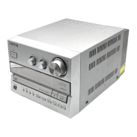
Detailed specifications for the main unit, including tuner and amplifier.
Specifications for the CD player section.
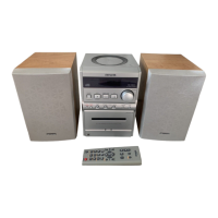
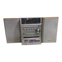
Specifications for the speaker system.
Critical safety warning regarding laser beam exposure during servicing.
Cautionary notes on potential hazardous radiation exposure.
Warnings in Finnish (Varoitus) and Swedish (Varning) about laser exposure.
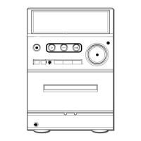
Wiring diagram for the main unit, section 1 of 3.
Detailed schematic for the main unit, covering 1/3 of the overall diagram.
Wiring diagram for front panel, key inputs, and headphone output.
Schematic diagram for the front panel and key inputs.
Wiring diagram for the amplifier section.
Schematic diagram for the amplifier section.
Wiring diagram for the power transformer section.
Schematic diagram for the power transformer section.
Wiring diagram for the tuner section.
Schematic diagram for the tuner section.
Pinout and function for IC LC876748A-5Z30.
Pinout and function for IC LC78646E.
Pinout and function for IC LC72131D-N.
Procedures for clock, VT (LW/MW/FM), and DC balance adjustments.
Procedures for IF adjustment (MW) and tracking adjustments (MW/LW/FM).
Procedure to check and adjust clock frequency.
Procedures for CD performance checks like jitter and playability.
Procedure to measure and verify laser current output.
Details on operating modes within the CD test mode.
Diagram showing the exploded view of the mechanical components.
List of mechanical parts with part numbers.
Table mapping basic color symbols to their corresponding color names.
Exploded view diagram of the CD mechanism (part 1 of 2).
Parts list for the CD mechanism (part 1 of 2).
Exploded view diagram of the CD mechanism (part 2 of 2).
Parts list for the CD mechanism (part 2 of 2).
List of accessories and their part numbers.
List of miscellaneous parts for CX-LEM60 / CX-LEM61.
List of miscellaneous parts for the CZA-3 model.
List of miscellaneous parts for the 3ZG-3 model.
List of miscellaneous parts for the 3ZG-2 model.
Step-by-step guide for disassembling the speaker units.
List of parts specific to the SX-LEM60 speaker model.
| CD Player | Yes |
|---|---|
| FM Tuner | Yes |
| Bluetooth | No |
| Weight | 4.5 kg |
| Cassette Deck | Yes |
| Remote Control | Yes |
| Speakers | 2-way bass reflex |
| Power Output | 30W per channel |
| Tuner | AM/FM |