Do you have a question about the Aiwa XR-H1100 and is the answer not in the manual?
Safety instructions for laser beam exposure during servicing.
Precautions for safely replacing the optical block.
Specifications for FM, MW, LW, and SW tuner sections.
Specifications for amplifier, equalizer, and speakers.
Specifications for cassette deck, CD player.
Specifications for FM, MW, LW, and SW tuner sections.
Specifications for amplifier, equalizer, and speakers.
Specifications for cassette deck, CD player.
List of ICs, transistors, and diodes.
List of components on the main circuit board.
List of components on the main circuit board.
Coding system for chip capacitors.
List of connectors, filters, jacks, and coils.
List of components on the front circuit board.
Coding system for chip capacitors.
List of connectors and filters.
List of switches and circuit boards (Pro, Tuner).
Coding system for chip capacitors.
List of connectors and VM circuit board components.
Explanation of how chip resistor part codes are structured.
Illustrations and pinouts for transistors 2SC3052 and RN1410.
Illustrations and pinouts for various transistors.
Wiring diagram for the main circuit board.
Wiring diagram for the VM circuit board.
Wiring diagram for the 10-pin connector board.
Wiring diagram for the main circuit board.
Wiring diagram for AC2 circuit board.
Wiring diagram for AC1 switch circuit board.
Wiring diagram for the sub-transformer circuit board.
Schematic diagram for the main circuit board.
Schematic diagram for the VM circuit board.
Schematic diagram for the 10-pin connector board.
Schematic diagram for the main circuit board.
Schematic diagram for the main circuit board.
Schematic diagram for the main circuit board.
Schematic diagram for the VM circuit board.
Schematic diagram for the Processor circuit board.
Schematic diagram for the 10-pin connector board.
Wiring diagram for the main circuit board.
Wiring diagram for AC2 circuit board.
Wiring diagram for AC1 switch circuit board.
Wiring diagram for the sub-transformer circuit board.
Wiring diagram for AC1 circuit board.
Wiring diagram for AC2 circuit board.
Wiring diagram for sub-transformer circuit board.
Wiring diagram for AC1 switch circuit board.
Schematic diagram for AC2 circuit board.
Schematic diagram for AC1 circuit board.
Schematic diagram for sub-transformer circuit board.
Schematic diagram for AC1 switch circuit board.
Schematic diagram for the tuner circuit board.
Wiring diagram for the tuner circuit board.
Wiring diagram for the tuner circuit board.
Schematic diagram for the tuner circuit board.
Layout and pin assignments for the FL display grid.
Pin connections for the FL display anode.
Block diagram of the BU9990-03FS IC.
Block diagram of the LC72131D IC.
Block diagram of the BU1920FS IC.
Block diagram of the LA1837NL IC.
Block diagram of the M62445AFP IC.
Block diagram of the NJM2152M IC.
Block diagram of the M62463AFP IC.
Block diagram of the M62449FP IC.
Description of the UPD780228GF-034-3BA IC pins and functions.
Description of the UPD780228GF-034-3BA IC pins and functions.
Description of the M65849BFP631D IC pins and functions.
Test points for tuner adjustments in EZ, K modes.
Test points for tuner adjustments in HR mode.
Procedure to check tuner clock frequency.
Adjustment and check for MW VT.
Adjustment procedure for SW VT.
Adjustment procedure for LW VT.
Check procedure for FM VT.
Procedures for tracking adjustments.
Check procedure for FM tracking.
IF adjustment procedure for AM(MW).
Adjustment for DC balance and mono distortion.
Practical service figures for the FM section.
Practical service figures for the MW section.
Practical service figures for the LW section.
Practical service figures for the SW section.
Exploded views of main assemblies (HT-SYNK).
Exploded views of other components (DIODE T3, PLATE).
Part list for panels, covers, and windows.
Part list for screws, holders, and fasteners.
List of ICs, transistors, and diodes.
List of components on the main circuit board.
Explanation of chip resistor code structure.
Illustrations and pinouts for transistors 2SC3052 and RN1410.
Layout and pin assignments for the FL display grid.
Pin connections for the FL display anode.
Wiring diagram for the main circuit board.
Wiring diagrams for front and key circuit boards.
Schematic diagram for the main circuit board.
Schematic diagrams for front circuit boards.
Description of the UPD78046HGF-032-3B9 IC pins and functions.
Description of the UPD78046HGF-032-3B9 IC pins and functions.
Exploded views of main unit assemblies (tray, window, cabinet).
Exploded views of specific components (badge, earth plate).
Part list for main unit components (tray, window, cabinet).
Part list for tapping screws and other fasteners.
List of ICs, transistors, and diodes.
List of components on the main circuit board.
List of capacitor codes, connectors, and filters.
Component list for the front-1 circuit board.
Explanation of chip resistor code structure.
Illustrations and pinouts for transistors.
Illustrations and pinouts for transistors.
Wiring diagram for the main circuit board.
Wiring diagrams for front circuit boards.
Schematic diagram for the main circuit board.
Schematic diagrams for front circuit boards.
Wiring diagram for the deck circuit board.
Wiring diagrams for head circuit boards.
Adjustment procedures for the deck section.
Procedures for tape speed and azimuth adjustments.
Checks for PB sensitivity and frequency response.
Adjustments for REC/PB sensitivity and response.
Practical service figures for the deck section.
Description of the M38503M4-094FP T4 IC pins and functions.
Description of the M38503M4-094FP T4 IC pins and functions.
Block diagram of the HA12211 IC.
Block diagram of the CXA1553P IC.
Exploded views of main unit assemblies.
Exploded views of other components.
Part list for cassette mechanism components.
Part list for tapping screws and other fasteners.
Spring application details for the cassette mechanism.
Exploded views of head circuit boards.
Exploded views of other components (PH, RPH).
Exploded views of solenoids and deck circuit board.
Exploded views of Deck 1 components.
Part list for cassette mechanism components.
Part list for tapping screws and other fasteners.
List of ICs, transistors, and diodes.
List of components on the main circuit board.
Explanation of chip resistor code structure.
Illustration and pinout for transistor RN1410.
Layout and pin assignments for the FL display grid.
Pin connections for the FL display anode.
Description of the LC866448W-5L20 IC pins and functions.
Block diagram of the BA3835F IC.
Wiring diagram for the main circuit board.
Schematic diagram for the main circuit board.
Exploded views of main unit assemblies.
Exploded views of specific components.
Part list for main unit components.
Part list for tapping screws and other fasteners.
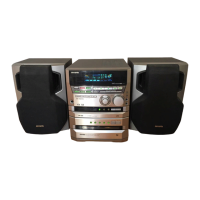
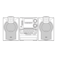
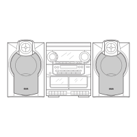
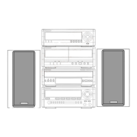
Instructions for disassembling speaker units (Types 1, 2, 3).
Procedures for removing and attaching speaker panels.
List of tools needed for speaker disassembly.
Parts list for SX-NAVH1200 speakers.
Parts list for SX-CR677 speakers.
List of included accessories like IB and RC UNIT.
Reference list for electrical components.
Reference list for mechanical components.
| CD Player | Yes |
|---|---|
| Remote Control | Yes |
| Tuner | Digital |
| Equalizer | Yes |
| Tuner Bands | AM/FM |
| Cassette Deck | Double |