EasyManua.ls Logo

Aiwa XR-H220MD User Manual

Aiwa XR-H220MD
60 pages
To Next Page IconTo Next Page
Page #1 background imageLoading...
Page #1 background image
BASIC TAPE MECHANISM : TN-591SW-143
MD / CD STEREO SYSTEM
XR-H220MD
S/M Code No. 09-997-413-6R1
EZ,K
SERVICE MANUAL
DATA
BASIC CD MECHANISM : 4ZG-1 Z3RNSMDJM
BASIC MD MECHANISM : ZZG-7 DM
SYSTEM
XR-H220MD
CASSIVER
CX-NH220MD
SPEAKER
SX-NH220 YSC
SX-NH220 YSC9
REVISION
This Service Manual is the "Revision Publishing" and replaces "Simple Manual"
(S/M Code No. 09-997-413-6T1).
If requiring information about the CD mechanism, see Service Manual of 4ZG-1, S/M
Code No.09-992-325-4N2.
Question and Answer IconNeed help?

Do you have a question about the Aiwa XR-H220MD and is the answer not in the manual?

Aiwa XR-H220MD Specifications

General IconGeneral
CD PlayerYes
MD Player/RecorderYes
TunerFM/AM
TypeMini System
Speakers2-way speaker system

Summary

Aiwa XR-H220MD Service Manual Overview

Aiwa XR-H220MD Specifications

Main Unit and Speaker System Specifications

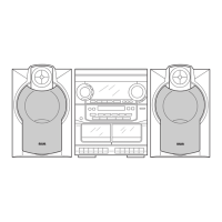
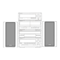
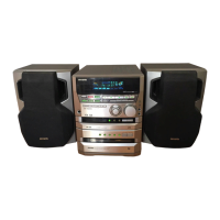
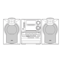
Details specifications for the main unit and speaker system, including dimensions and power.

Audio and Mechanism Specifications

Covers specifications for cassette, CD, and MD sections, laser, and audio performance.

Laser Safety Precautions During Servicing

Optical Block Replacement Safety

Safety guidelines for replacing optical blocks, emphasizing ESD precautions.

MD Mechanism Disassembly Procedures

Removing MD Mechanism Components

Steps for removing the 7ZG-9, MD mechanism, and shield top.

Disassembling Head and Related Parts

Instructions for removing the head and associated plates.

MD Mechanism Further Disassembly

Removing Head and Plate Assemblies

Detailed steps for removing the head, side plates, and slide plates.

Accessing and Removing Mechanism Sub-parts

Procedures for removing BOSS and 7ZG-3 A1 components.

Main Circuit Board Electrical Parts List

Main Unit Block Diagram (Part 1)

Interconnections of Main Circuit Boards

Illustrates the signal flow and connections between the main, front, and interface circuit boards.

MD Mechanism Block Diagram (Part 2)

MD System Signal Flow

Shows the functional blocks and signal paths within the MD mechanism.

Main Unit Block Diagram (Part 2)

Detailed Circuit Board Interconnections

Further details on signal paths and connections for the main unit's circuitry.

MD Mechanism Block Diagram (Part 3)

MD Mechanism Component Signal Paths

Additional details on the signal flow within the MD mechanism components.

Front Circuit Board Wiring Diagram

Front Circuit Board Schematic Diagram

MD Circuit Board Schematic Diagram

Interface Circuit Board Wiring Diagram

Interface Circuit Board Schematic Diagram

Mechanism Wiring Diagrams

CD Test Mode Operations

Starting and Exiting CD Test Mode

Procedures for entering and exiting the CD test mode.

MD Test Mode Procedures

Starting and Exiting MD Test Mode

Steps to start, exit, and switch to servo standby mode for MD testing.

MD Mechanism and Laser Output Checks

Procedures for checking sled operation and laser power output in MD test mode.

MD Test Mode: Mechanism and Switch Checks

MD Test Mode: Servo Operation Checks

Focus Search and Spindle Kick Verification

Procedures to check focus search and spindle kick operations.

Focus Servo and All Servos ON Check

Steps to verify focus servo and ensure all servos are operational.

Tuner Section Adjustment Procedures

Tuner Frequency and Sensitivity Adjustments

Covers adjustments for clock frequency, MW/LW VT, IF, and tracking.

Deck Section Adjustment Procedures

Tape Speed and Azimuth Adjustments

Procedures for adjusting tape speed and azimuth.

Sensitivity and Response Adjustments

Covers PB sensitivity and REC/PB frequency response adjustments.

Practical Service Performance Figures

MD Block Adjustment Procedures

Temperature Compensation and Laser Power

Adjustments for temperature compensation and laser power output.

Auto Sequence Adjustment Steps

Procedures for auto sequence adjustments like EFB, IVR, AGC, and Tracking.

MD Block Advanced Adjustments

MO and PIT Disc Gain Adjustments

Adjusting IVR, EFB, Focus/Tracking/Sled gains for MO and PIT discs.

Error Rate Checks for PIT and MO Discs

Procedures for checking error rates on PIT and MO discs.

MD Block Error Rate Verification

Mechanical Parts List (1/1)

Mechanical Assembly Exploded View

Tape Mechanism Exploded View

Tape Mechanism Parts List

MD Mechanism Exploded View (1/4)

MD Mechanism Exploded View (2/4)

MD Mechanism Exploded View (3/4)

MD Mechanism Parts List (3/4)

MD Mechanism Exploded View (4/4)

MD Mechanism Parts List (4/4)

Speaker Unit Disassembly Instructions

Speaker Parts List (1/1)

Related product manuals