EasyManua.ls Logo

Aiwa XR-H560MD User Manual

Aiwa XR-H560MD
72 pages
To Next Page IconTo Next Page
Page #1 background imageLoading...
Page #1 background image
BASIC TAPE MECHANISM : 6ZM-1 AR3
MD / CD STEREO SYSTEM
XR-H560MD
S/M Code No. 09-993-412-1R2
EZ,K
SERVICE MANUAL
REVISION
SYSTEM
XR-H560MD
CD–CASSEIVER
CX-NH560MD
SPEAKER
SX-WNH898
DATA
BASIC CD MECHANISM : 4ZG-1 Z3RNSMDJM
BASIC MD MECHANISM : ZZG-6 D
This Service Manual is the "Revision Publishing" and replaces "Simple Manual"
(S/M Code No. 09-993-412-1T2).
If requiring information about the CD mechanism, see Service Manual of 4ZG-1, S/M
Code No.09-992-325-4N2.
Question and Answer IconNeed help?

Do you have a question about the Aiwa XR-H560MD and is the answer not in the manual?

Aiwa XR-H560MD Specifications

General IconGeneral
CD PlayerYes
MD Player/RecorderYes
TunerFM/AM
CD Player TypeSingle Disc
Remote ControlYes
Frequency Response20Hz - 20kHz
TypeMini System
ConnectivityHeadphone
FunctionsCD, MD
AmplifierBuilt-In
Speakers2-way speakers

Summary

Specifications

Main Unit CX-NH560MD

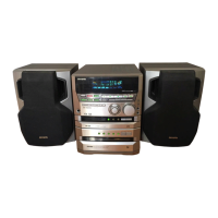
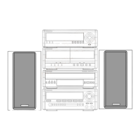
Detailed specifications for the main unit of the CX-NH560MD system.

MD Recorder Section

Technical specifications related to the MD recorder functionality.

Cassette Deck Section

Technical specifications for the cassette tape mechanism.

Speaker System SX-WNH898

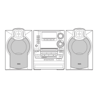
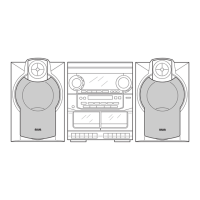
Specifications for the included SX-WNH898 speaker system.

Compact Disc Player Section

Technical specifications of the compact disc playback capabilities.

Accessories and Package List

List of items included in the product package.

Protection of Eyes from Laser Beam During Servicing

Precaution to Replace Optical Block (KSS-213F)

Precaution to Replace Optical Block (KMS-260A)

Disassembly Instructions

1. Disassembling the MD Block

Step-by-step guide for disassembling the MD component.

2. Disassembling the MD Block and Service Position

3. Disassembling the Elevator

4. Disassembling the Elevator Block

Cassette Mechanism Disassembly Instructions

Note on Before Starting Repair

CD Service Position

Instructions for preparing the unit for CD servicing.

Electrical Main Parts List

IC

List of integrated circuits used in the main board.

Transistor

List of transistors used in the main board.

Transistor Illustration

IC Block Diagram

IC, BA7762AFS

Block diagram for the BA7762AFS integrated circuit.

IC, BU2099FV

Block diagram for the BU2099FV integrated circuit.

IC, MM1454XFBE

Block diagram for the MM1454XFBE integrated circuit.

IC, BA6417F

IC, CXA2523AR

Block diagram for the CXA2523AR integrated circuit.

IC, BA3880FS

IC, BD7910FV

Block diagram for the BD7910FV integrated circuit.

Block Diagram-1 (Main)

Block Diagram-2 (MD)

Schematic Diagram-2 (PT)

Schematic Diagram-3 (Main 2/2)

Wiring-3 (Front)

Schematic Diagram-4 (Front)

Wiring-4 (Interface)

Schematic Diagram-5 (Interface)

Wiring-5 (MD)

Schematic Diagram-6 (MD)

Wiring-6 (Tuner)

Schematic Diagram-7 (Tuner)

Wiring-7 (Mecha)

FL Grid Assignment/Anode Connection

Test Mode < MD >

1. How to Start Up the MD Test Mode

Procedure to start the MD test mode by connecting AC power.

2. Checking the MD Test Mode

How to check the MD test mode indicators and status.

5. Checking the Sled Operation

Procedure for checking the sled motor operation.

6. Checking the Laser Output

How to check and adjust the laser output power levels.

7. Checking the Operation of Loading Mechanism/OWH

Procedure to check the loading mechanism and optical pickup operation.

8. Checking the Indication and Turning On/Off of Each Switch

Verifying switch functions and display indications.

Test Mode < CD >

1. How to Start the CD Test Mode

Procedure to start the CD test mode by connecting AC power.

3. Function Descriptions on the CD Test Mode

Details on functions and operations within CD test mode.

(Electrical Adjustment)

1. Temperature Compensation Adjustment

Procedure for adjusting temperature compensation for MD unit.

2. Laser Power Adjustment

Guide for adjusting playback and recording laser power.

3. Auto Sequence Adjustment (EFB/IVR/Focus AGC/Tracking AGC Adjustments)

Procedure for automatic adjustment of servo parameters.

3-2. Checking the IVR, EFB, Focus/Tracking/Sled Gains of the MO Disc

3-3. Adjusting the PIT Disc

4. Error Rate Check (PIT Disc)

5. Recording/Playback Error Rate Check (MO Disc)

Electrical Adjustment < Deck Section >

1. Tape Speed Adjustment

Procedure to adjust the tape speed for the cassette deck.

2. Azimuth Adjustment

Procedure to adjust the azimuth of the tape head.

Practical Service Figure < Deck Section >

4. REC/PB Frequency Response Adjustment

5. REC/PB Sensitivity Check

< Tuner Section >

< FM Section >

Specifications and checks for the FM tuner section.

< MW Section >

Specifications and checks for the MW tuner section.

Practical Service Figure < Tuner Section >

1. Clock Frequency Check

Procedure to check clock frequency in the tuner section.

5. FM VT Check

Checking voltage for FM tuning.

7. LW Tracking Adjustment

Adjusting LW tracking for optimal signal reception.

IC Description

IC, LC876580W

Description of the LC876580W integrated circuit.

IC, CXD2652AR

IC, CXP81952

Mechanical Parts List 1/1

Mechanical Exploded View 1/1

MD Mechanism Exploded View 1/4

MD Mechanism Parts List 1/4

Parts list for the MD mechanism (part 1 of 4).

MD Mechanism Exploded View 3/4

MD Mechanism Parts List 3/4

Parts list for the MD mechanism (part 3 of 4).

MD Mechanism Exploded View 4/4

MD Mechanism Parts List 4/4

Parts list for the MD mechanism (part 4 of 4).

Tape Mechanism Exploded View 1/1

Tape Mechanism Parts List 1/1

Spring Application Position

Speaker Disassembly Instructions

Speaker Parts List 1/1

IC Description

IC, CXD2652AR

Description of the CXD2652AR integrated circuit.

Related product manuals