Do you have a question about the Aiwa Z-R550 and is the answer not in the manual?
Lists system parts, mechanisms, and revision information for Aiwa models.
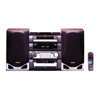
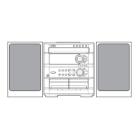
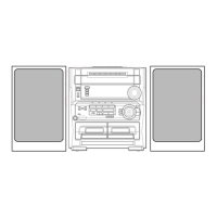
Identifies the Aiwa Z-R550/R554/R555/R560 stereo cassette receiver models.
Provides detailed technical specifications for tuner, amplifier, and cassette deck sections.
Details specifications for the CD player and various speaker systems.
Outlines general power requirements, consumption, unit dimensions, and weight.
Important safety warnings regarding laser beam exposure during maintenance procedures.
Precautions for replacing the optical pickup block to prevent damage.
Step-by-step guide for safely discharging electrolytic capacitors before servicing.
Essential checks for the microcomputer's HOLD terminal and reset function before replacement.
Lists main electrical components including ICs, transistors, and diodes with part numbers.
Visual representations of transistors and the coding system for chip resistors.
Illustrates block-level connections between main PCB, front PCB, and CD mechanism.
Shows functional blocks and signal flow within the tuner section.
Details electrical connections and routing on the main circuit board.
Provides detailed electronic schematic for the main circuit board.
Presents electronic schematic for the front PCB for specific models.
Shows electrical wiring and connections for the front PCB in specified models.
Details electrical wiring and connections for the front PCB for the 550HE model.
Displays electronic schematic for the front PCB of the 550HE model.
Illustrates functional blocks of critical ICs like BU9262AFS, BU4094BCF, BA3835S, M62439SP, and LA1837.
Provides wiring and schematic diagrams for the sub-circuit board.
Shows wiring for AC power connections (AC1/AC2).
Details electronic schematic for the tuner's front-end circuitry.
Illustrates functional blocks of the LC72131D tuner IC.
Maps grid numbers to functions for the FL display panel.
Shows how anode pins are connected for the FL display.
Detailed description of pin functions for the main microprocessor.
Detailed description of pin functions for the LC72131D tuner IC.
Identifies test points and settings for tuner adjustments.
Identifies test points and settings for tape deck adjustments.
Procedures for checking tuner performance parameters like sensitivity and distortion.
Procedures for checking tape deck performance like speed, frequency response, and sensitivity.
Exploded view of the CD mechanism (6ZG-1 SDSHNM) with part references.
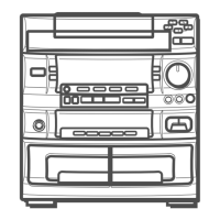
Exploded view of the main chassis assembly with part references.
List of all mechanical parts for the main chassis assembly.
Exploded view of the tape mechanism, showing assembly details for the first half.
List of mechanical parts for the tape mechanism, corresponding to the first exploded view.
Exploded view of the tape mechanism, showing assembly details for the second half.
List of mechanical parts for the tape mechanism, corresponding to the second exploded view.
Instructions for disassembling speaker unit Type 1.
Instructions for disassembling speaker unit Type 2.
Instructions for disassembling speaker unit Type 3.
List of parts for the SX-ZR55 speaker system.
List of parts for the SX-ZR25 speaker system.
List of parts for the SX-R276 speaker system.
List of parts for the SX-FZR75 speaker system.
Lists all accessories and items included in the product package.
Glossary of terms and abbreviations used in the electrical sections.
Glossary of terms and abbreviations used in the mechanical sections.
| Type | Mini Hi-Fi System |
|---|---|
| Tuner Bands | AM/FM |
| Output Power | 50W (25W per channel) |
| CD Player | Yes |
| Inputs | AUX |
| Outputs | Headphones |
| Tape Deck | Double Cassette Deck |
| Equalizer | Yes, Graphic Equalizer |