EasyManua.ls Logo

Aiwa Z-HT530 User Manual

Aiwa Z-HT530
45 pages
To Next Page IconTo Next Page
Page #1 background imageLoading...
Page #1 background image
SERVICE MANUAL
DATA
COMPACT DISC STEREO
CASSETTE RECEIVER
BASIC TAPE MECHANISM : ZZM-3 PR1NM
BASIC CD MECHANISM : 6ZG-1 ZRDM
Z-HT530
K, EZ
S/M Code No. 09-004-428-1R1
REVISION
This Service Manual is the "Revision Publishing" and replaces "Simple Manual"
Z-HT530 (K, EZ), (S/M Code No. 09-002-428-1T1).
If requiring information about the CD mechanism, see Service Manual of
6ZG-1, (S/M Code No. 09-001-338-7N2).
If requiring information about the Stereo Turntable, see Service Manual of
PX-E860 (K), (S/M Code No. 09-993-322-0R4).
Z–HT530 (EZ)
SPEAKERSYSTEM
CD
CASSEIVER
SX–ZHT530
SX–CR677
CX–ZHT530
REMOTE
CONTROLLER
Z–HT530 (K)
RC–ZAS10
PX–E860
STEREO
TURNTABLE
w
w
w
.
x
i
a
o
y
u
1
6
3
.
c
o
m
Q
Q
3
7
6
3
1
5
1
5
0
9
9
2
8
9
4
2
9
8
T
E
L
1
3
9
4
2
2
9
6
5
1
3
9
9
2
8
9
4
2
9
8
0
5
1
5
1
3
6
7
3
Q
Q
TEL 13942296513 QQ 376315150 892498299
http://www.xiaoyu163.com
Question and Answer IconNeed help?

Do you have a question about the Aiwa Z-HT530 and is the answer not in the manual?

Aiwa Z-HT530 Specifications

General IconGeneral
BrandAiwa
ModelZ-HT530
CategoryStereo System
LanguageEnglish

Summary

Product Information

System Components Overview

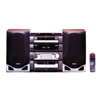
Lists main system components like CD, Speaker, Remote, and Turntable.

Specifications

Tuner Specifications

Details for FM, MW, and LW tuner sections, including tuning range and sensitivity.

Amplifier and Speaker Specifications

Power output, distortion, inputs, outputs, and speaker compatibility.

Mechanism and General Specifications

Details for cassette, CD, speaker systems, and main unit power/dimensions.

Licensing Information

Information on Dolby Laboratories and BBE Sound, Inc. licensing.

Laser Safety During Servicing

Laser Beam Exposure Warnings

Warnings and cautions regarding laser beam exposure during servicing.

Optical Block Replacement Precautions

Guidelines for safely replacing the optical block, including ESD precautions.

Repair Preparation Notes

Power Supply Capacitor Discharge

Procedure to safely discharge electrolytic capacitors before commencing repair.

Microcomputer Exchange Pre-checks

Checks to perform before replacing the microcomputer, focusing on HOLD terminal.

Microcomputer Troubleshooting

Microcomputer Reset Procedure

Steps for performing a forced reset on the microcomputer.

Microcomputer Soldering Check

Ensuring good soldering before concluding microcomputer failure.

Electrical Main Parts List

Integrated Circuits (IC)

List of integrated circuits with part numbers and descriptions.

Transistors, Diodes, and Main C.B. Components

Lists of transistors, diodes, and main circuit board components.

Electrical Main Parts List (Continued)

Capacitors (C374-C810)

Detailed list of capacitors with part numbers and specifications.

Electrical Main Parts List (Continued)

Capacitors, Connectors, and Fuses

List of various capacitors, connectors, and fuses with part details.

Electrical Main Parts List (Continued)

Capacitors, Connectors, LEDs, and Switches

List of capacitors, connectors, LEDs, and switches with part information.

Electrical Main Parts List (Continued)

Capacitors, Connectors, Fuses, and Relays

List of capacitors, connectors, fuses, protectors, and relays.

Component Identification

Chip Resistor Part Coding

Explanation of how chip resistor part codes are structured.

Transistor Illustrations

Visual representations of common transistor pinouts and types.

Wiring Diagram - 1 (Main / VM)

Schematic Diagram - 1 (Main 1/4: Amp Section / VM)

Schematic Diagram - 2 (Main 2/4: Deck Section)

Schematic Diagram - 3 (Main 3/4: Tuner Section)

Schematic Diagram - 4 (Main 4/4: Prologic Section)

Wiring Diagram - 2 (Micon)

Schematic Diagram - 5 (Micon / Deck)

Wiring Diagram - 3 (Cntl / Key CD)

Schematic Diagram - 6 (Cntl / Key CD)

Wiring Diagram - 4 (Amp 1F)

Schematic Diagram - 7 (Amp 1F)

Wiring Diagram - 5 (Amp 2F)

Schematic Diagram - 8 (2F Amp)

Wiring Diagram - 6 (PT)

Schematic Diagram - 9 (PT)

Wiring Diagram - 7 (Deck)

IC Description: LC876580W-5P66

Pin Functions and Descriptions

Details pin assignments and functions for the LC876580W-5P66 IC.

IC Description: LC876580W-5P66 (Continued)

Pin Functions and Descriptions (Continued)

Details pin assignments and functions for the LC876580W-5P66 IC.

IC Block Diagrams

BU2099FV IC Block Diagram

Functional block diagram for the BU2099FV IC.

LC72131D IC Block Diagram

Functional block diagram for the LC72131D IC.

IC Block Diagrams (Continued)

M61506FP and LA1843 IC Block Diagrams

Functional block diagrams for M61506FP and LA1843 ICs.

IC Block Diagrams (Continued)

BU1920FS and M62463AFP IC Block Diagrams

Functional block diagrams for BU1920FS and M62463AFP ICs.

IC Block Diagrams (Continued)

BA7762AFS, BD3876KS2, and M62491FP IC Block Diagrams

Functional block diagrams for BA7762AFS, BD3876KS2, M62491FP ICs.

FL Display Grid Assignment and Anode Connection

FL Display Grid Assignment

Layout and numbering of the FL display segments.

FL Display Anode Connection

Mapping of FL display anodes to specific pins and segments.

FL Display Anode Connection (Continued)

FL Display Anode Connection Table

Table detailing FL display anode connections for various segments and digits.

Adjustment Procedures

Tuner and Micon Adjustments

Instructions and diagrams for adjusting tuner and micon circuits.

Deck Mechanism Adjustments

Instructions for adjusting deck mechanism speed and head alignment.

Tuner Section Adjustments

Frequency and VT Checks

Procedures for checking clock frequency and voltage (VT) for MW and FM.

Tracking and IF Adjustments

Steps for tracking and IF adjustments in tuner sections.

Balance, Output Level, and Separation Adjustments

Procedures for DC balance, output level, and FM separation adjustments.

Deck Section Adjustments

Tape Speed and Azimuth Adjustments

Procedures for adjusting tape speed and head azimuth for DECK 1 and DECK 2.

Playback Response and Sensitivity Checks

Methods for checking PB frequency response and sensitivity.

REC/PB Adjustments and μ-CON OSC

Procedures for REC/PB adjustments and μ-CON OSC calibration.

Mechanical Exploded View

Mechanical Parts List

Mechanical Parts List (1/1)

List of mechanical parts with reference numbers and descriptions.

Tape Mechanism Exploded View

Tape Mechanism Parts List

Tape Mechanism Parts List (1/1)

List of tape mechanism parts with reference numbers and descriptions.

Speaker Disassembly and Panel Removal

Speaker Unit Disassembly

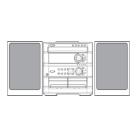
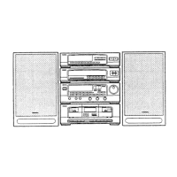
Instructions for disassembling speaker units (Types 1, 2, 3).

Front Panel Removal Procedure

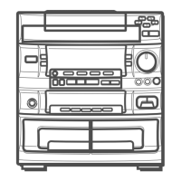
Step-by-step guide on how to remove the front panel (PANEL, FR).

Speaker and Accessory Parts Lists

Speaker Parts List (SX-ZHT530)

List of parts for the SX-ZHT530 speaker system.

Speaker Parts List (SX-CR677)

List of parts for the SX-CR677 speaker system.

Accessories and Package List

List of included accessories and package contents.

Related product manuals