Removing magneto control cable handlebar end and contact breaker
vent pipe and front engine plate.
Removing both oil pipes (be careful with spanner manipulation at
crankcase end).
Removing outer portion front chain case.
Removing clutch assembly, engine sprocket and chain (see note).
Removing rear portion front chain case.
Removing crankcase release pipe.
Removing bolts passing through rear engine plates and crankcase, then
loosen top and bottom gear box fixing bolts, loosen also footrest rod and
central stand pivot bolt which tend to clamp the crankcase.
Removing bottom front engine bolt.
Removing crankcase assembly from frame. When a duplex tube frame
is not used, wheel machine off the stand, the frame will open and facilitate
removal of crankcase.
NOTE—Use a tyre lever with one end bent at right angle to prise off the
lower magneto sprocket. To remove top sprocket, slacken off all timing
cover screws, use tool B 4018 (see Fig. 10), inserted between magneto
sprocket and magneto body. With the armature nut removed, a light tap
on the tool will dislodge sprocket. A tool to prevent the engine turning
(top gear engaged) whilst unscrewing the gear box mainshaft nut and also
engine sprocket nut is shown in Fig. 8, which is easy to fabricate.
Separating the crankcase. Before attempting to separate the crankcase,
the oil pump plunger must be removed by taking off the cap at the rear
end of the pump plunger housing, then remove the screwed body (No. 6.
Fig. 9), and guide pin (5). Insert a piece of stout wire or wheel spoke in
the plunger hole and pull out the pump plunger,
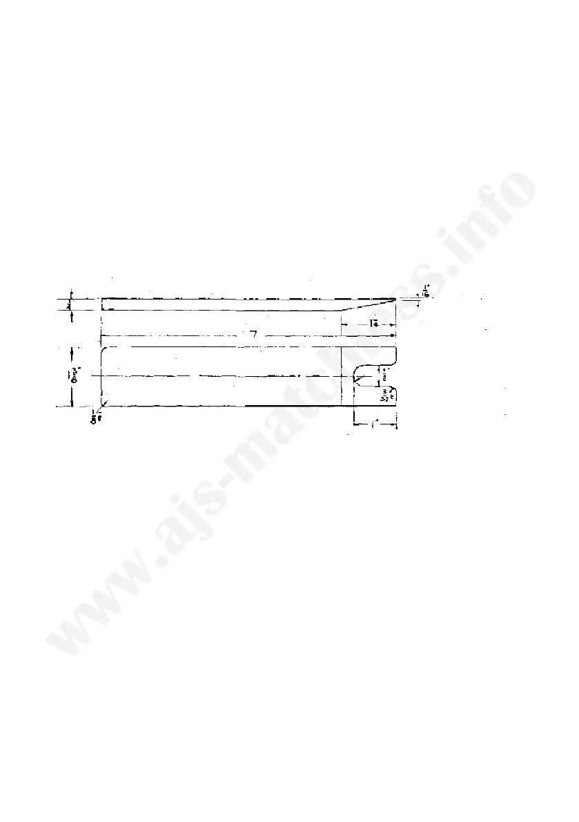
Removing the small timing pinion. This pinion is a taper fit on the shaft
and needs a tool or puller to extract it from the shaft. Put the tool in
position and lightly tighten the draw bolt (do not over tighten), then give
the end of the draw bolt a sharp blow with a light hammer, the pinion
will then come away from the shaft.
Separating the flywheels. The flywheel separating tool B 2140 as des-
cribed for the 250 c.c. model, can also be used for the Scrambler. As an
FIG 10 Magneto sprocket remover
48