The oil pump. The face of the oil pump body, where it joins the crank-
case, must be perfectly flat also free from bruises and blemish; otherwise
the oil “pick up” from the pump will be curtailed, as the pump will suck
air at this point. Use a little Wellseal as jointing compound on the pump
body when fitting.
There are more than one type of oil pump worm nut and pump pinions.
If at any time hew parts are fitted, check the new ones against the old
ones before they are installed. The pump pinions are of the three start
type. If the pump is dismantled, on assembly make sure the end plates do
not protrude over the pump body; they should be just below the pump
body.
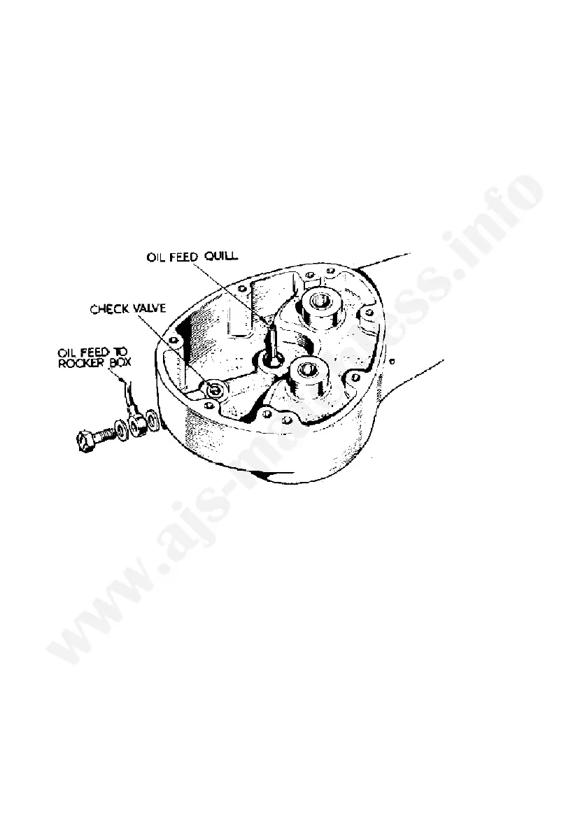
Check valve. A simple check valve (Fig. 11) is provided to prevent oil
seeping into the crankcase when the engine is stationary.
The bearing oil seal. A thin bronze bush is used in the timing side crank-
case, this does not constitute a bearing as it is simply an oil seal to stop
oil leaking past the roller bearing. 1964 models only.
Crankcase bearings. The design of the driving side bearings is unaltered.
Details for removal as described for earlier models still apply. A flanged
type roller bearing is now used in the timing side of the engine on all
single cylinder engines. The bearing sleeve is an interference fit in the
crankcase, to take it out the crankcase must be gently heated, then the
action of dropping the case on to a flat wood bench will dislodge the
sleeve.
Separating the crankcase. First take off the oil pump worm drive nut
which has a left hand thread. Take off the oil pump, retained by two nuts.
Remove the small timing pinion, which now has a parallel bore. With all
the bolts passing through the crankcase taken out the case can be parted,
the inner member for the roller bearing will remain on its shaft.
The flywheels. To take off the, inner member for the roller bearing use
two taper steel wedges behind the bearing, once a gap is formed a puller
can be used to extract the bearing member from its shaft.
FIG 11 Oil check valve
51