Do you have a question about the Akai AA-5500 and is the answer not in the manual?
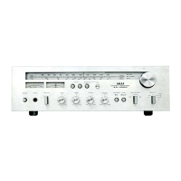
Detailed specifications for the AA-5800 model, including power output, input sensitivity, and distortion.
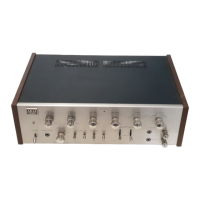
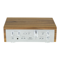
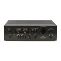
Detailed specifications for the AA-5500 model, including power output, input sensitivity, and distortion.
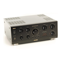
Detailed specifications for the AA-5200 model, including power output, input sensitivity, and distortion.
Instructions for removing the upper cover of the amplifier unit.
Instructions for removing the bottom plate of the amplifier unit.
Diagram showing the arrangement of main internal components within the AA-5800 model.
Diagram showing the arrangement of main internal components within the AA-5500 model.
Diagram showing the arrangement of main internal components within the AA-5200 model.
Procedure for measuring the frequency response of the amplifier using specified equipment.
Procedure for measuring the power band width of the amplifier using specified equipment.
Procedure for measuring the hum and noise levels of the amplifier.
Procedure for calculating the signal-to-noise ratio of the amplifier.
Instructions for adjusting the idling current of the main amplifier using a specified procedure.
Instructions for adjusting the output signal waveform for clipping symmetry.
Procedure for adjusting the zero electrical potential on the main amplifier of the AA-5800.
Detailed procedure for adjusting the Electric Protection Circuit (EPC) of the amplifier.
Overview of component layouts for the AA-5800 amplifier, detailing circuit board components.
Detailed views of component placement on various circuit boards for the AA-5800 amplifier.
Further composite views detailing component placement on circuit boards for the AA-5800.
Overview of component layouts for the AA-5500 amplifier, detailing circuit board components.
Detailed views of component placement on various circuit boards for the AA-5500 amplifier.
Further composite views detailing component placement on circuit boards for the AA-5500.
Overview of component layouts for the AA-5200 amplifier, detailing circuit board components.
Detailed views of component placement on various circuit boards for the AA-5200 amplifier.
Schematic diagram for the Equalizer and Microphone Amplifier PC Board (55-5315) of the AA-5800.
Schematic diagram for the Microphone Effects Amplifier PC Board (55-5329) of the AA-5800.
Schematic diagram for the Mute PC Board (55-5313) of the AA-5800.
Schematic diagram for the Pre Tone Amplifier PC Board (55-5312) of the AA-5800.
Schematic diagram for the Filter Amplifier PC Board (55-5314) of the AA-5800.
Schematic diagram for the Main Amplifier PC Board (55-5311) of the AA-5800 (Part 1).
Schematic diagram for the Relay PC Board (55-5316) of the AA-5800.
Schematic diagram for the Regulator PC Board (55-5310) of the AA-5800.
Schematic diagram for the Power Supply PC Board (55-5309) of the AA-5800.
Schematic diagram for the Microphone Effects Amplifier PC Board (55-5049) of the AA-5500.
Schematic diagram for the Equalizer and Microphone Amplifier PC Board (55-5024) of the AA-5500.
Schematic diagram for the Pre Tone Amplifier PC Board (55-5022) of the AA-5500.
Schematic diagram for the Filter PC Board (55-5023) of the AA-5500.
Schematic diagram for the Main Amplifier PC Board (55-5021) of the AA-5500 (Part 1).
Schematic diagram for the Power Supply PC Board (55-5017) of the AA-5500.
Schematic diagram for the Regulator PC Board (55-5020) of the AA-5500.
Schematic diagram for the Equalizer Amplifier PC Board (55-5211) of the AA-5200.
Schematic diagram for the Loudness Control PC Board (55-5210) of the AA-5200.
Schematic diagram for the Pre Tone Amplifier PC Board (55-5022) of the AA-5200.
Schematic diagram for the Main Amplifier PC Board (55-5209) of the AA-5200 (Part 1).
Schematic diagram for the Power Supply PC Board (55-5208) of the AA-5200.
Schematic diagram for the Regulator PC Board (55-5020) of the AA-5200.
| Input Sensitivity | 2.5mV (MM), 150mV (line) |
|---|---|
| Speaker Load Impedance | 4Ω to 16Ω |
| Frequency Response | 20Hz to 20kHz |
| Signal to Noise Ratio | 70dB (MM) |
| Channel Separation | 55dB (MM) |