J
James KhanJul 31, 2025
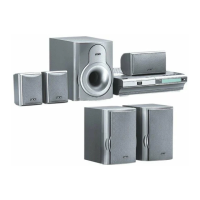
Why is there no sound coming from my Akai Home Theater System?
- CCharles PerryAug 1, 2025
If there's no sound, several factors could be at play. Ensure the power plug is correctly inserted and that the output and input cables are securely connected. Also, verify that the volume isn't set to the minimum. The input format may also be incorrect.