EasyManua.ls Logo

Alarm.Com ADC-480Q - User Manual

Alarm.Com ADC-480Q
6 pages
Print Icon
To Next Page IconTo Next Page
Loading...
Copyright © 2022 Alarm.com | www.alarm.com | v4.0
1
ADC-480Q Module | User Guide
ADC-480Q Module
USER GUIDE REV 3.6
Introduction
The Alarm.com ADC-480Q Module enables wireless reporting of all alarms
and other system events from compatible control panels using the LTE
wireless (cellular) network. The module can be used as the primary
communication path for all alarm signaling, or as a backup to a telephone
line connection to the central monitoring station. The wireless alarm
signaling and routing service is operated by Alarm.com. The LTE Module also
features integrated support for Alarm.com’s emPowersolution with built-
in Z-Wave capabilities.
Installation
The ADC-480Q Module is meant for professional installation only.
Installation consists of inserting the module into a compatible alarm panel,
attaching the antenna, and performing an LTE phone test at the panel. See
the Module Diagram at the end of this installation guide for a component
overview.
Installers are responsible for ensuring host devices are tested and compliant
with the applicable FCC and ISED rule parts, including the required host
labeling as shown in the Regulatory Informationsection in this document.
Troubleshooting LEDs
Status LEDs indicate network and module status. Figure 1 below shows the
location of the status LEDs on the LTE module.
Figure 1: Status LEDs
Table 1 below describes the LED functions.
Table 1: LED Functions
LED
Function
L1
Error LED. Flashes 1 to 8 times in an 8-second interval to indicate
specific error. See Table 2 for errors and common fixes.
L2
Panel Communication and Z-Wave status messages. Flashes every
time the module communicates with the panel and flashes in
patterns to indicate Z-Wave status.
L3
LTE Communication. Flashes every time the LTE signal level is
checked and when packets are exchanged with Alarm.com.
L4
LTE Signal Level. Flashes 0 to 5 times to indicate signal strength, or
toggles on/off slowly when communicating with Alarm.com servers.
L5
Z-Wave Error LED. See Table 3 for error descriptions.
LED Details
LED L1 (red)
L1 flashes when there is an error. The number of flashes indicates the error
number. If there are two or more errors at the same time, the errors will
flash one after the other. The LED will stay off for at least four seconds
between errors.
Table 2: Errors flashed on L1 (red)
Number of
flashes
Error and solution
1
Module cannot communicate with the panel. Perform a power
cycle on the panel. If the error persists lift the module out of
the panel and re-insert it. If the error is still observed try a
different module. Finally, if that does not fix the problem try a
different panel.
2
then 4 The module provisioning process could not be completed.
2 then 5
The module provisioning process could not be completed
because the module is currently roaming on the carrier’s
network.
3
The module is trying to register on the LTE network. If it
persists for more than a few minutes, the module is having
problems registering. Check L4 for signal level. If signal level is
lower than 2 “bars”, change the panel’s location or use a
remote antenna option.
4
The module is registered on the LTE network but cannot
connect with Alarm.com. Contact Alarm.com Technical
Support.
5
Radio portion of the module is not working correctly. If this
persists for more than a few minutes the module may need to
be replaced. This error is extremely rare so verify that the
module is flashing 5 times.
6
This is an error only if it persists for more than a minute.
Otherwise, it’s just an indication that the module is fixing an
unusual condition regarding communication with the LTE
network.
7
The module is not compatible with this panel type. Please
insert a compatible module.
8
If it persists, the account may have been set up incorrectly.
Contact Alarm.com Technical Support. You will be asked to
check the serial number of the module.
LED L2 (yellow)
L2 flashes with every communication between the module and the panel.
Normal pattern calls for a series of quick flashes every two seconds in Idle
Mode or four seconds in PowerSave Mode. It also occasionally flashes in
patterns to indicate Z-Wave status. See the table below for a description of
various possibilities.
L1 L2 L3 L4 L5
Question and Answer IconNeed help?

Do you have a question about the Alarm.Com ADC-480Q and is the answer not in the manual?

Overview

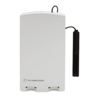
The Alarm.com ADC-480Q Module is a device designed to enable wireless reporting of alarms and other system events from compatible control panels using the LTE cellular network. It can serve as the primary communication path for alarm signaling or as a backup to a telephone line connection for central monitoring. The module also integrates support for Alarm.com's emPower™ solution, which includes built-in Z-Wave capabilities.

Installation and Setup:

The ADC-480Q Module is intended for professional installation. The installation process involves inserting the module into a compatible alarm panel, attaching the antenna, and performing an LTE phone test at the panel. Installers are responsible for ensuring that host devices are tested and compliant with applicable FCC and ISED rule parts, including required host labeling.

Technical Specifications:

  • Power Requirements: 6V nominal
  • Standby Current: 30mA (10mA in PowerSave Mode)
  • Peak Current: 1.7 A
  • Operating Temperature: 32 to 120°F (0 to 49°C)
  • Storage Temperature: -30 to 140°F (-34 to 60°C)
  • Max. Relative Humidity: 90% non-condensing
  • Cellular Networks: 4G LTE Cat-1 (EG91-NAX) or 4G LTE Cat-M1 (BG95-M6), compatible with VERIZON and ATT.
  • Dimensions (H x W): 4 1/16 x 1 7/8 in.

Cellular Antenna Guidance:

The module uses Quectel BG95-M6 or Quectel EG91-NAX. Recommended antennas are PIFA (planar inverted-F) dipole type with 50 ohm impedance and VSWR less than or equal to 2. The cellular antenna(s) should be positioned at a minimum of 20cm from the user and any other antenna elements or transmitters. Maximum peak gains for cellular antennas vary by frequency:

  • 698-716 MHz: 5.5 dBi
  • 777-787 MHz: 5.8 dBi
  • 824-849 MHz: 6.0 dBi
  • 1710-1780 MHz: 4.9 dBi
  • 1850-1915 MHz: 7.9 dBi

The Z-Wave antennas on the device are not detachable, and power settings are not adjustable by the end user.

Troubleshooting and Maintenance:

The module features several LEDs (L1, L2, L3, L4, L5) that indicate network and module status, as well as specific errors.

LED L1 (red) - Error LED:

Flashes 1 to 8 times in an 8-second interval to indicate specific errors. If multiple errors occur, they flash sequentially with a 4-second pause between errors.

  • 1 flash: Module cannot communicate with the panel. Solutions include power cycling the panel, re-inserting the module, trying a different module, or trying a different panel.
  • 2 then 4 flashes: Module provisioning process could not be completed.
  • 2 then 5 flashes: Module provisioning failed due to roaming on the carrier's network.
  • 3 flashes: Module is attempting to register on the LTE network. If persistent, check L4 for signal level; if below 2 "bars," change panel location or use a remote antenna.
  • 4 flashes: Module is registered on LTE but cannot connect to Alarm.com. Contact Alarm.com Technical Support.
  • 5 flashes: Radio portion of the module is not working correctly. If persistent, the module may need replacement (rare error).
  • 6 flashes: Module is fixing an unusual communication condition with the LTE network (only an error if persistent for over a minute).
  • 7 flashes: Module is not compatible with this panel type. Insert a compatible module.
  • 8 flashes: Account may be set up incorrectly. Contact Alarm.com Technical Support and provide the module's serial number.

LED L2 (yellow) - Panel Communication and Z-Wave Status:

Flashes with every communication between the module and the panel. In Idle Mode, it flashes quickly every two seconds; in PowerSave Mode, every four seconds. It also flashes in patterns to indicate Z-Wave status.

LED L3 (yellow) - LTE Communication:

Flashes with every communication between the module and its radio unit in Idle Mode, and with every communication with Alarm.com in Connected Mode. In PowerSave Mode, this LED flashes in unison with L2.

LED L4 (green) - LTE Signal Level:

Flashes 0 to 5 times to indicate signal strength (0-5 bars). The number of bars may not correspond to cell phone displays. 5 bars indicate the strongest signal. Signal level updates every 10 seconds if fluctuating, or every 30 seconds if stable. If L4 is not flashing, it indicates:

  • Module is in PowerSave Mode.
  • Module just powered up.
  • No LTE coverage in the area. Alarm.com recommends a steady signal level of 2 or higher for proper operation. In Connected Mode, the LED toggles on and off.

LED L5 (yellow) - Z-Wave Error LED:

Indicates Z-Wave errors.

Module States (Modes):

The module operates in three main states:

  • Idle Mode: AC power is OK, and the module is not currently communicating with Alarm.com. L1 flashes errors, L2 indicates panel communication, L3 indicates radio unit communication, L4 shows signal level, and L5 flashes Z-Wave errors.
  • PowerSave Mode: Module just powered up, AC power is down, or AC power was recently restored and the battery is recharging. L1, L4, and L5 are inactive. L2 indicates panel communication, and L3 flashes with the same pattern as L2.
  • Connected Mode: The module is currently communicating with Alarm.com. L1 flashes errors, L2 indicates panel communication and Alarm.com communication, L3 indicates Alarm.com communication, L4 alternates two seconds on/off, and L5 is inactive.
  • Sleep Mode: The panel is not connected to AC power, or there is an AC power failure, and the battery level is low. The module connects to Alarm.com to send a signal but otherwise draws minimal power. Buffered messages from Alarm.com may be received when power is restored.

Improving Wireless Signal Strength:

  • Install the module above ground level, as high as possible within the structure.
  • Install the module near or adjacent to an outside-facing wall.
  • Avoid installing the module inside a metal structure or close to large metal objects or ducts.
  • Follow antenna positioning guidelines, as some antennas require specific orientation.
  • Contact Alarm.com technical support for antenna options.

Regulatory Information:

  • FCC ID: YL6-143480Q, IC: 9111A-143480Q.
  • Complies with FCC Part 15.249 and ISED RSS-210.
  • The host device must display specific labeling information regarding FCC and IC IDs for the module and its cellular components (Quectel BG95-M6 or EG91-NAX).
  • Complies with part 15 of the FCC Rules: operation is subject to two conditions—no harmful interference, and acceptance of any received interference.
  • Changes or modifications not expressly approved by Alarm.com can void the user's authority to operate the equipment.
  • This equipment has been tested and found to comply with Class B digital device limits. If it causes harmful interference to radio or television reception, corrective measures include reorienting the antenna, increasing separation, connecting to a different circuit, or consulting a technician.
  • ISED compliance: contains licence-exempt transmitter(s)/receiver(s) that comply with Innovation, Science and Economic Development Canada's licence-exempt RSS(s). Operation is subject to two conditions—no interference, and acceptance of any interference.

Alarm.Com ADC-480Q Specifications

General IconGeneral
BrandAlarm.Com
ModelADC-480Q
CategoryControl Unit
LanguageEnglish

Related product manuals