Alcatel-Lucent 300 Series Access Point | Installation Guide 2
External Antenna Connectors
The OAW-AP304 and OAW-IAP304 access points are
equipped with three external antenna connectors on the
front corners of the access point.
Figure 2 External Antenna Connector
USB Interface
The 300 Series is equipped with a USB port for connectivity
with cellular modems and other USB client devices. When
powered by an 802.3at or DC power source, the USB port can
supply power up to 5W/1A. The USB interface is disabled
when the access point is powered by an 802.3af PoE source
(power-save mode).
Console Port
The serial console port is located at the back of the device
and is a 4-pin connector covered by a dust cover. An optional
serial adapter cable (AP-CBL-SER) is sold separately to
connect the device to a serial terminal or a laptop for direct
local management.
Ethernet Port
The 300 Series access points are equipped with one 10/100/
1000Base-T auto-sensing MDI/MDX Ethernet port. This port
supports wired-network connectivity, in addition to Power
over Ethernet (PoE) from IEEE 802.3af and 802.3at compliant
power sources.
This device accepts 56V DC (802.3at), or 48V DC (802.3af)
nominal as a standard powered device (PD) from power
sourcing equipment, including PoE midspan injector or a
PoE-sourcing network infrastructure.
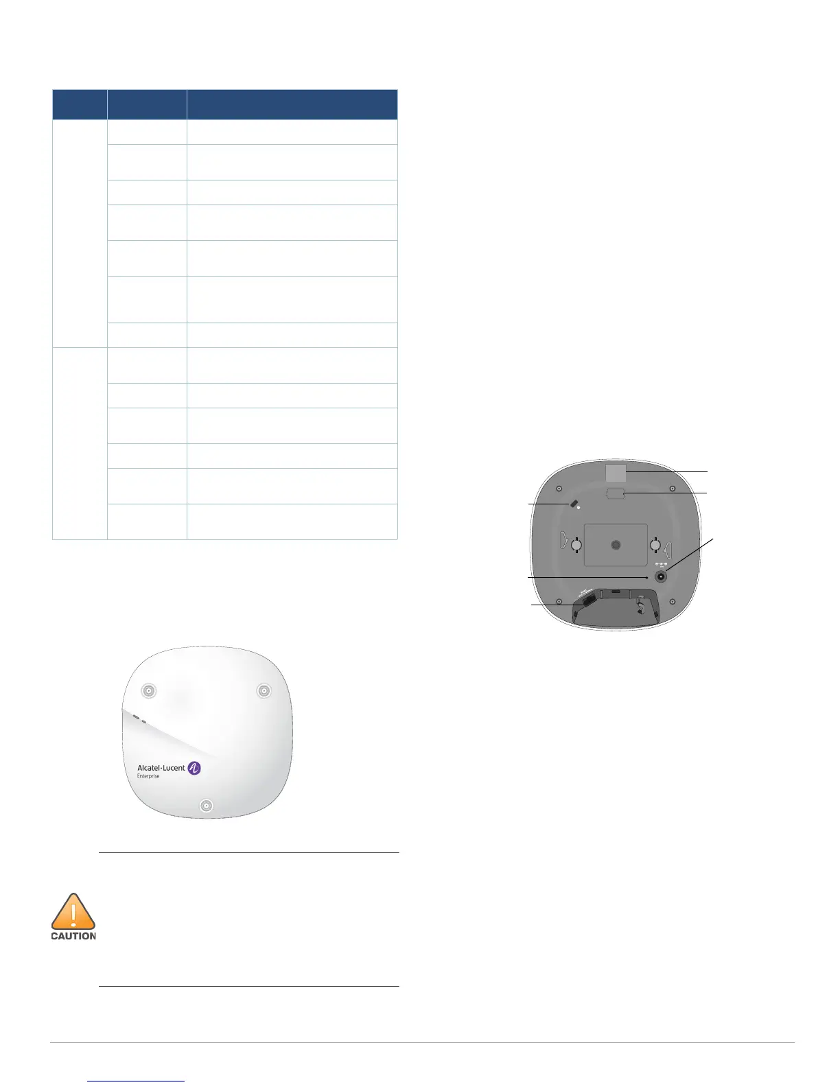
Figure 3 Back Panel
Kensington Lock Slot
The 300 Series access points are equipped with a Kensington
lock slot for additional security.
Reset Button
To reset the 300 Series access points to factory default
settings, press and hold down the reset button using a small,
narrow object such as a paper clip while the (I)AP is powered
on.
DC Power Socket
If PoE is not available, an optional Alcatel-Lucent AP-AC-
12V30B power adapter kit (sold separately) can be used to
power the 300 Series access points.
Additionally, a locally-sourced AC-to-DC adapter (or any DC
source) can be used to power this device, as long as it
complies with all applicable local regulatory requirements
and the DC interface meets the following specifications:
12 Vdc (+/- 5%) and at least 18W
Center-positive 2.1/5.5 mm circular plug, 9.5 mm length
Table 1 300 Series LEDs Status in Normal Mode
LED Color/State Meaning
System
Status
(Left)
Off Device powered off
Green-
Blinking
Device booting, not ready for use
Green- Solid Device ready for use, no restrictions
Green-
Flashing
Device ready for use, uplink negotiated
in sub optimal speed (<1Gbps)
Amber- Solid Device ready for use; power-save
mode (802.3af PoE)
Amber-
Flashing
Device ready for use; power-save
mode (802.3af PoE), uplink negotiated
in sub optimal speed (<1Gbps)
Red- Solid System error condition
Radio
Status
(Right)
Off Device powered off, or both radios
disabled
Green- Solid Both radios enabled in access mode
Green-
Blinking
One radio enabled in access mode
Amber- Solid Both radios enabled in monitor mode
Amber-
Blinking
One radio enabled in monitor mode
Alternating One radio enabled in access mode,
other in monitor mode
External antennas for this device must be installed by an
Alcatel-Lucent Certified Field Expert (ACFE) or other
Alcatel-Lucent-certified technician, using manufacturer-
approved antennas only.
The Equivalent Isotropically Radiated Power (EIRP) levels
for all external antenna devices must not exceed the
regulatory limit set by the host country/domain.
Installers are required to record the antenna gain for this
device in the system management software.
Console Port
Ethernet Port
USB Port
Reset Button
DC Power
Socket
Kensington Lock
 Loading...