10
244/244OS Series Tooling Alcoa Fastening Systems
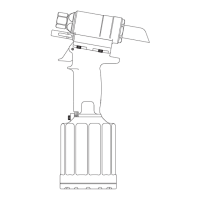
12. Remove Nose Adapter (9) from front of Head, Plug
& Seat Assembly (15). (Figs. 1 & 9) (Fig. 10 for
244OS Model).
13. If Seat (74) is damaged, contact your Huck
representative. If Seat Assembly (80) is damaged, it
can be removed by using Seat Removal Tool
(126136) optionally available. NOTE: Seats should
not be reused. They should be replaced.
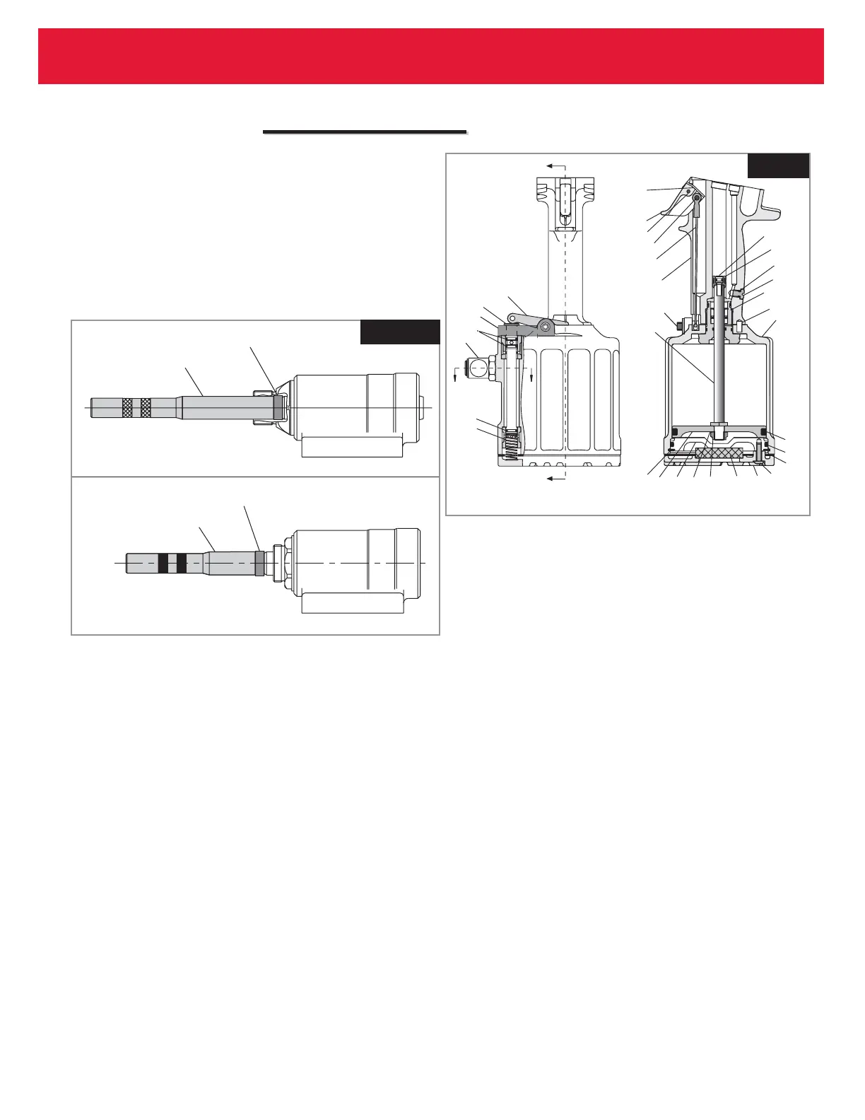
14. With a small punch and hammer, drive Roll Pin (4)
that retains the Trigger (5) from the Handle (1).
Remove Trigger Pin (3). Remove ball cable end
from Throttle Arm (68) and pull Cable Assembly (2)
out of Handle (1). (Fig. 3)
15. Remove Pivot Screw (64) and Lever Guard (94) from
Throttle Arm (68). Remove Throttle Arm. Pull
Throttle Valve (67) out of cylinder. Remove Spring
(65) (Fig3).
16. Remove Bleed Plug (40) from handle (Fig3).
17. Hold tool inverted in vice. Unscrew three Button
Head Screws (55) with 1/8 hex key (Fig3).
18. Remove Bottom Plate (56), Gasket (54) and Muffler
(57) (Fig3).
19. Remove Retaining Ring (62) from Cylinder
Assembly (51) (Fig3).
20. Install Screws (55) into Cylinder Head (60).
Carefully pry under screws to remove cylinder head.
21. Push air piston all the way down in cylinder, lay tool
on its side. Hold Locknut (58) with a 9/16 socket and
extension and with 7/64 hex key, remove piston
Screw (34).
22. Grip Locknut (58) under Air Piston with pliers and
pull piston and rod assembly from handle and
cylinder assembly. CAUTION: Care must be taken
not to scratch piston rod or cylinder during
removal.
24. Turn cylinder and handle upside down and secure in
a vise.
25. With a 1 3/8 socket and extension, remove Gland
Assembly (41). Handle and cylinder will now
separate (Fig3).
26. Push Piston Assembly (33) out of handle. Push out
from top to bottom. CAUTION: A plastic or
wooden drift must be used to avoid damaging
the handle bore.
27. Remove Swivel Assembly (86) from cylinder. Swivel
Assembly may be disassembled to replace seals
(32 & 87) if necessary. (Fig. 9)
28. To remove Polyseal (43) from Gland Assembly (41),
remove Retaining Ring (45) and Spacer (44). (Fig.
9)
Fig. 2a
Fig. 2a
Fig. 2b
Fig. 2b
 Loading...