12
244/244OS Series Tooling Alcoa Fastening Systems
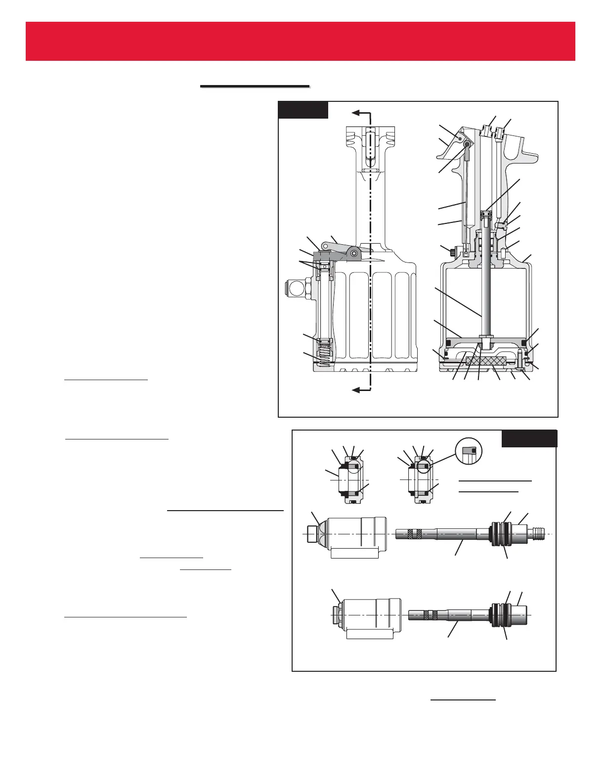
12. If Seat Assembly (80) is being replaced, push
seat and seal assembly in using soft drift. Take
care not to damage ball seat surface. (Fig. 9)
13. Assemble hydraulic Piston (18) with new seals
(16,17). Lubricate with LUBRIPLATE or
PARKER SUPER-O-LUBE. (Fig. 9)
14. Install Nose Adapter (9) on front of head. (Use
VIBRA-TITE Huck P/N 505125 on threads).
Torque to 50-60 ft. lbs. (Fig. 7)
15. Assemble Front Gland (12) Gland Cap (11) O-ring
(14) Back-up Ring (13) and Polyseal (6). Thread
Piston Assembly Tool 123111-2 (244), 123111-8
(244OS) onto Piston (18). Slide complete Front
Gland Assembly and (Wiper Seal (10) 244 only)
over Piston Assembly Tool onto Piston. (Fig. 7)
16. Press entire piston and gland assembly into
head. Remove Piston Assembly Tool from
piston. (Fig. 7)
17. 244 Model: (Fig. 9)
Place Seals (20) and (24) on Rear Gland (19).
Push complete assembly into head and screw
in End Cap (21), and torque to 50 - 60 ft. lbs.
244OS Model: (Fig. 10)
Place seals (20 & 24) on Rear Gland (19). Push
complete assembly into head and screw in End
Cap (21), torque to 50-60 ft. lbs. Thread Stop (89)
into End Cap (21) two turns, thread Locknut (92)
onto Piston Stop (89) and leave loose. For
adjustment, refer to M
EASURING TOOL STROKE
section of this manual (Page 20).
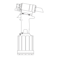
18. Install Quad-Ring (72) and Spacer. Slide Reservoir
Plunger (73) in. {244OS Model:
Install Spring (93)
first, then Spring (71); 244 Model: Install two
Springs (71)}. Screw Housing/Spacer Assembly
into head. (Fig. 1)
19. 244 Model Only (Fig. 1 & 9)
Push Pintail Deflector (22) onto rear of Piston (18).
20. Place O-ring (39) on Plug (40) and screw
assembly into Handle (1). (Fig. 6)
21. Install Pull (29) and Return (25) Gland Assemblies in
handle. Push head down on glands. Place tool in a
vise Head down and install 4 Screws (69) and torque
to 170 inch pounds. (Fig. 6 & 9)
22. Tool is now completely assembled except for relief
and check valves. See F
ILL AND BLEED
procedure for
replacement of valve components.
Fig. 7a
Fig. 7b
 Loading...