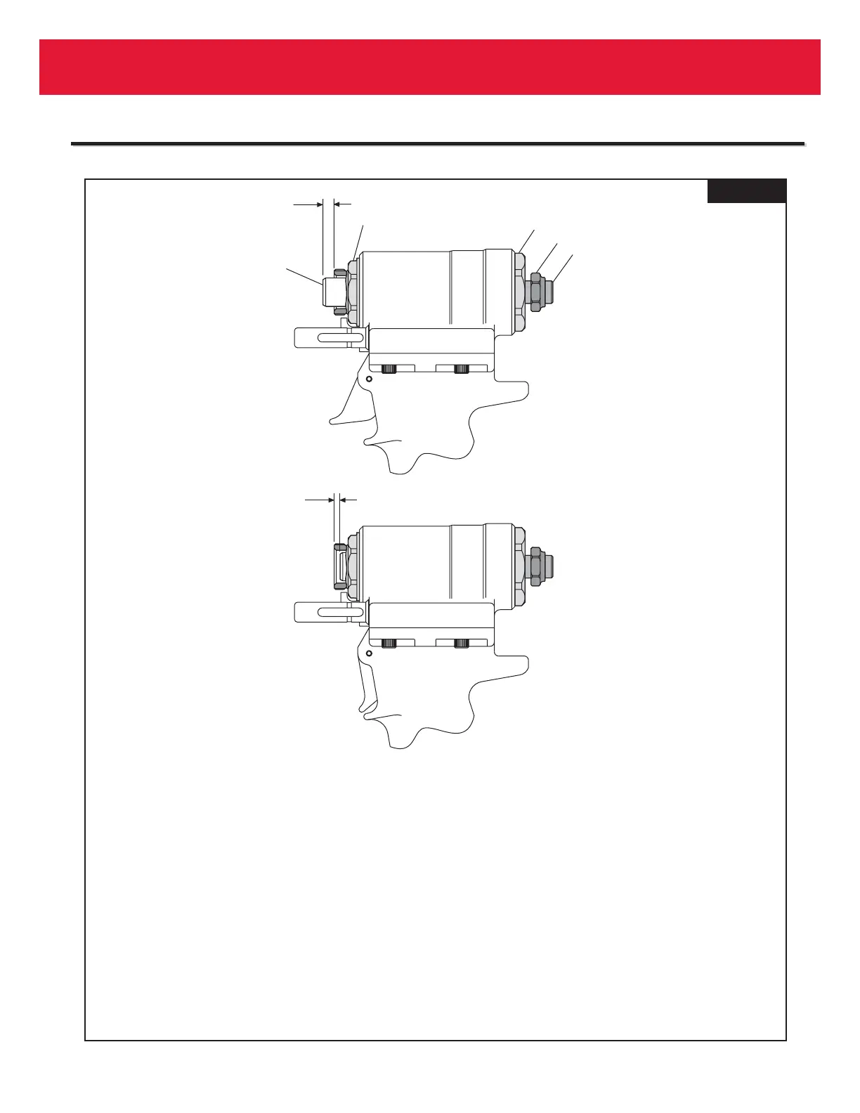
FIG. 11
ADJUSTING STROKE
1. Measure distance "A" from face of Hydraulic Piston (18) to face of Nose Adapter (9).
This distance should be approximately equal to .247 inches.
2. Cycle tool and hold piston back by keeping the trigger depressed. Measure distance
"B" as above.
3. STROKE = A+B
4. Adjust Piston Stop (89) clockwise to reduce dimension "B" (decreasing stroke) and
counterclockwise to increase "B" (increasing stroke). Repeat step 2.
5. When desired stroke has been reached, hold Piston Stop (89) with a ¼" hex key and
with a ¾" open end wrench tighten Locknut (92) against End Cap (21).