S.S.C. HD A Module - Installation and user’s guide - 030718 - 5
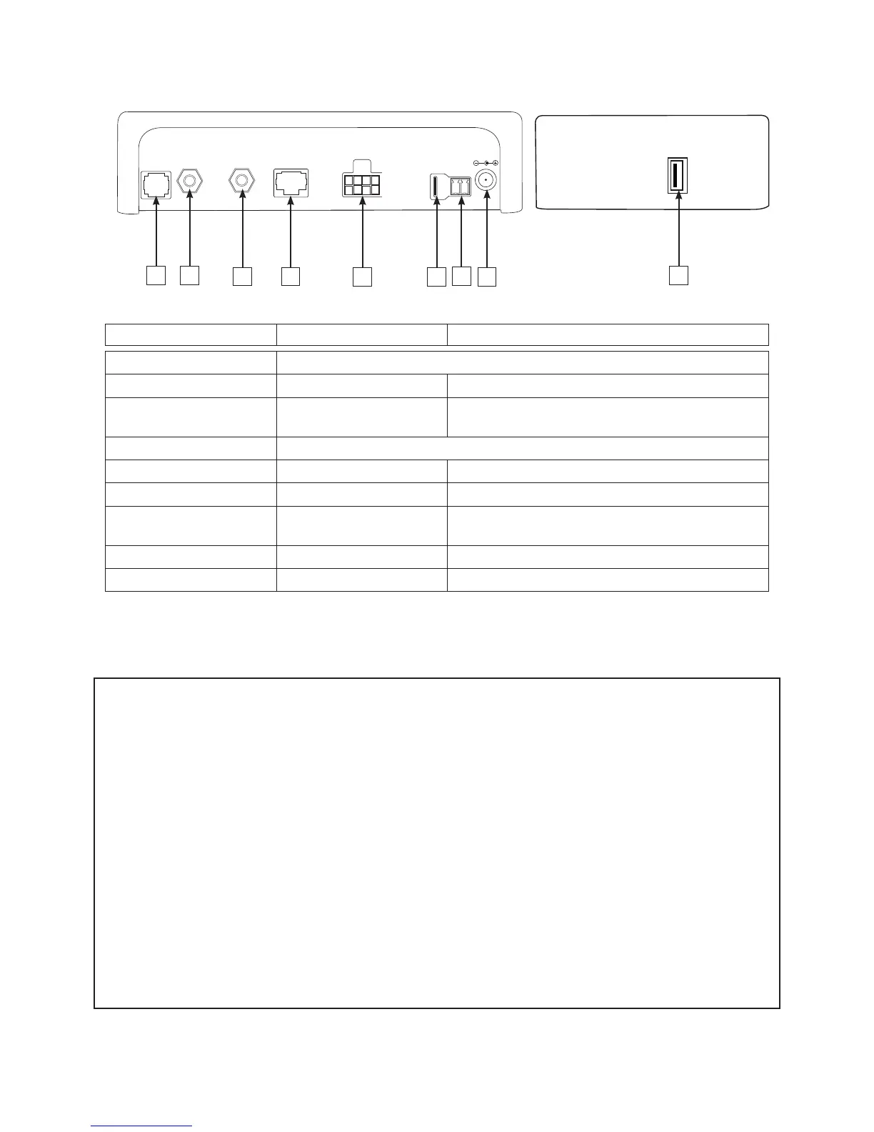
S.S.C. wiring diagram
N° : description Type of connection Input and output description
1 : RC Optionnel: Interface utilisateur déportée.
2 : LNB in F Type coaxial Connection with the sat-unit’s LNB.
3 : Out to demo F Type coaxial Connection used to connect the SSC module to the
receiver or satellite TV.
4 : Data For Alden’s use only
5 : USB USB Used to update the data.
6: MOTOR Power Used for the motorisation of the sat-unit.
7: CONTACT Spade connector Folding security system connected to the car
ignition.
8 : TV OUT TV output Used to power up a 12V/3A max. TV
9 : 10-15V DC Jack DC 12V SSC Power supply
Warning - Reminder :
• The system must be in a vertical position in a well ventilated space.
• Do not place the unit near a source of heat or humidity.
• Do not leave the unit direclty in the sunlight.
• The ventilation grille must be free. Do not block.
• Do not use existing coaxial circuits. The quality of the picture can be affected. Each link will weaken the
signal. Cables of a different type can also change the quality of the picture.
• In all cases :
- A direct wiring (no links) with a 5A fuse must go from the unit to the battery for the + wire.
- A direct wiring (no links) must go from the unit to the battery for the - wire.
- A direct wiring (no links) with a 3A fuse must go from the S.S.C. module to the + after ignition
located on the ignition key or on the fuse module.
• When installating with existing wiring, make sure the 3 cases above are respected.
• Always use the provided cables
• The warranty will no longer be applicable if these instructions are not followed.
1 2
3
4
5
DATA
OUT TO
DEMO
LNB IN
14/18V 300mA
RC
10 - 15VDC
TV OUT
CONTACT
MOTOR SKEW
6
7
8
9
 Loading...