EasyManua.ls Logo

Aleko LM176 User Manual

Aleko LM176
2 pages
To Next Page IconTo Next Page
Page #1 background imageLoading...
Page #1 background image
- 1 -
User Manual of Electromagnetic Lock
ModelLM176
Technical Parameters:
A. Holding power: 280KGS B. Working Voltage: 24VDC
C. Working Current:250mA D. Safety mode: Power-on to lock, Power-off to open.
E. Typical InstallationFlushingA)、 HangingG
Installtion chart
Hanging Type Electromagnetic Lock Electromagnetic Lock fitting for all kinds of doors.
Flush Bonding Type
Typical Installation
STEP 1
A Fold template along dotted line.
B Place template against door and head frame.
C Drill holes as indicated on temple.
STEP 2
A Mount the armature palte to door using 1 rubber washer sandwiched between 2 steel washer(the rubber washer and 2 steel washer are installed on the
through sexnut between the armature plate and door).
STEP 3
A Install the mounting plate with 2 flat head screws(the 2 M5X5 flat head screws are installed in the solotted holes for adjustment).
B Adjust mounting plate so that it forms right angle with the armature plate.
C Using the mounting plate as a temple,drill the wire hole.
D Drill and remaining mounting screws.
STEP 4
A Instal magnet to mounting plate with 2 M4 screws supplied.
STEP 5
A Test all functions of this model(see wiring instruction).
Model
L1
L2
A
B
D
E
F
280GF/X
250
210
27
16.5
2.3
6
50.5
Question and Answer IconNeed help?

Do you have a question about the Aleko LM176 and is the answer not in the manual?

Aleko LM176 Specifications

General IconGeneral
KeypadYes
FinishSatin Nickel
HandingReversible
Number of Keys Included2
Power SourceBattery
Lock TypeDeadbolt

Summary

Electromagnetic Lock Technical Specifications

Lock Parameters and Safety

Details holding power (280KGS), working voltage (24VDC), current (250mA), and safety mode.

Typical Installation Types

Specifies Flushing and Hanging as typical installation methods for the lock.

Installation Procedure and Diagrams

Installation Charts and Dimensions

Provides diagrams and dimensions for hanging and flush bonding type locks.

Step-by-Step Installation

Guides users through template application, drilling, component mounting, and testing.

Armature Plate Mounting Details

Door Mounting Assembly

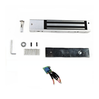
Illustrates how to mount the armature plate to the door using specific hardware.

Armature Plate Adjustment

Emphasizes not overtightening to allow automatic adjustment of the armature plate.

Electrical Connections

24VDC Power Connection

Details required power (0.5A) and how to connect positive and negative leads.

Swing Gate Opener Integration

Shows wiring for connecting the lock to an AS/GG swing gate opener system.