2
Application
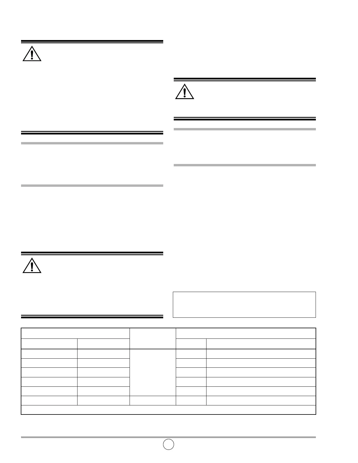
Meter Model
Adapters
Grease Gun Model Control Valve Model Part No. Description
575 and 585 Series
3530 and 3530-A
340062 Adapter Kit for Alemite Cordless Grease Guns
500, 525, 550, 555, 555-E 41531 1/8" NPTF (m) x 1/8" NPTF (m) x 1.00" Long
1056 and 4015 Series 7421-3 327899-6 1/8" NPTF (m) x 1/8" NPTF (m) x 1.50" Long
6320-3 327899-3 1/8" NPTF (m) x 1/8" NPTF (m) x 2.75" Long
6243-J3 and 6679-J3 306722 1/4" NPTF (m) x 1/8" NPTF (m) x 1.19" long
6243-J3E and 6679-J3E 6438 3530-B and 3530-C 327033 * 1/4" NPTF (m) x 1/4" NPTF (m) x 1.41" Long
* Included with Models 3530-B and 3530-C
Table 3 Electronic Grease Meter Adapters
Installation
WARNING
Prior to installation, the following safety pre-
cautions must be observed. Personal injury can occur.
1. Do not exceed the pressure rating of any component
in the system.
2. Rupture of components can inject grease into skin
and eyes, causing serious injury and possible amputa-
tion. If injured, seek immediate medical attention.
3. Protect all material and air supply lines from puncture
or damage. Check all lines for weak or worn conditions
prior to use.
CAUTION
Prior to meter installation, flush all contaminants by
pumping grease through the gun/system. Jammed
gears, damaged components, and inaccurate readings
can occur.
Apply thread sealant to all male pipe threads upon
installation.
NOTE: Table 3 shows the adapters for installing
the grease meter on grease guns and control
valves.
Maintenance
WARNING
Release all pressure within the system prior to
performing any maintenance procedure.
Repairs should only be performed by a qualified person
using original repair parts.
Read each step of the instructions carefully. Make sure a
proper understanding is achieved before proceeding.
Battery Replacement
NOTE: All meter values remain in memory.
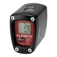
The batteries should be replaced once the battery icon
appears on the display. See Figure 1.
IMPORTANT: The meter will no longer register
should the battery icon begin to flash.
WARNING
Recycle or discard the used batteries properly.
Do not burn or puncture the batteries. Toxic materials
may be emitted which can cause personal injury.
CAUTION
Avoid touching the flat surfaces of the new batteries.
Skin oils can cause battery deterioration. Clean any sus-
pect battery with alcohol prior to installation.
Install the new Batteries positive terminal first.
•See Page 7.
Metering Gear Replacement
IMPORTANT: Install the gear with the magnets
as shown on Page 7.
Rotate the gear assembly to ensure the gears are
properly positioned.
SER 3530
Electronic Grease Meter
Revision (11-10) Alemite, LLC
Changes Since Last Printing
Reinstated battery cap kit
 Loading...