SER 7342 High-Capacity Reel
Revision (10-13) 10 Alemite LLC
10. Install U-Bolt (10) onto the delivery hose and to the Sheave
Assembly.
11. Install Washers (9) and Wing Nuts (8) onto the U-Bolt.
• Tighten the Wing Nuts securely.
Accessories Attachment and Pressurization
12. Install the control valve onto the delivery hose.
13. Pressurize the system.
• Check for leaks.
14. Install and secure the hose stop to the delivery hose at the
desired position.
15. Make sure the reel is latched then:
• instruct the assistant to let go of the Sheave Assembly
or
• carefully remove the clamp from the Sheave Assembly
16. Pull the delivery hose to disengage the Ratchet.
17. Allow the delivery hose to slowly retract onto the Sheave
Assembly.
Checking Spring Tension
18. Check to ensure the tension on the power spring
is sufficient to properly hold the hose stop
against the hose guide.
Should the power spring tension require
adjustment:
Adjusting Spring Tension
CAUTION
Do not overwind the power spring. Too much
tension reduces the life of the spring.
When the hose is fully extended from the
reel, the power spring should be a minimum
of 1/2 turn from a fully wound condition.
19. Release all pressure within the system.
WARNING
Disconnect the air supply line to the
pump’s motor.
Into an appropriate container, operate the
control valve to discharge remaining
pressure within the system.
20. Remove the control valve and the hose stop
from the delivery hose.
21. Pull the free end of the delivery hose through
the guide.
22. Rotate the Sheave Assembly in the required
direction.
23. Install the control valve and the hose stop.
24. Pressurize the system.
25. Check to ensure the tension on the power spring
is sufficient to properly hold the hose stop
against the hose guide.
26. Repeat steps 19 - 25 until the proper tension is
achieved.
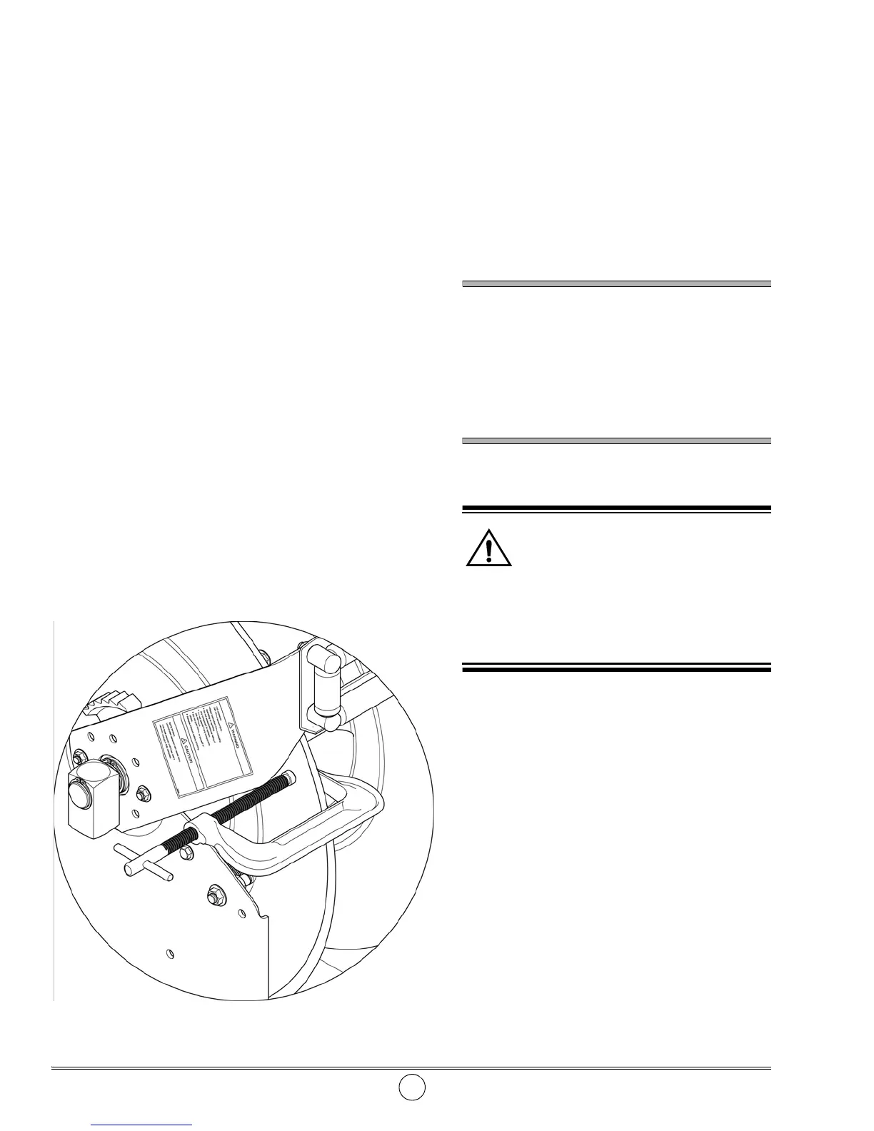
Figure 5 Clamp Attached to Sheave Assembly
 Loading...