. .
21
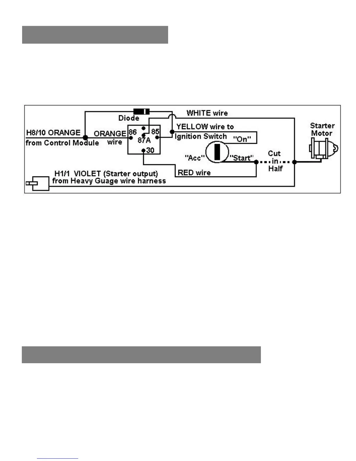
WIRING CONNECTIONS
H8/10 ORANGE
Wire
(Starter Disable Relay Output)
The ORANGE wire will provide a 500mA (-) negative output when the
security system is armed. A relay with a diode across the coil must be
used when interrupting the starter wire. If attaching more then one device
to this wire you must diode isolate each device.
H9: 2-PIN BLUE CONNECTOR FOR THE PROGRAM / VALET SWITCH:
Select a mounting location for the switch that is hidden but easily
accessible to the driver of the vehicle. Mount the valet switch in a hidden
but accessible location. Route and plug in the valet switch wires to the
control module.
H10: 2-Pin White Connector for LED Light
The LED light should be mounted in a highly visible location in the
dashboard, center console or dashboard face. Provide for at least a 6mm
space behind the LED light. Once a suitable location is chosen, drill a
6mm hole then press the LED housing into the hole. Route the LED wires
to the control module and plug it in.
AUTOMATIC OR MANUAL TRANSMISSION
A. AUTOMATIC/MANUAL TRANSMISSION VEHICLE:
Manual Transmission: When you are in manual transmission mode, you
also need to connect the Brown / Red wire to the emergency or handbrake
switch. An isolation diode must be used for the handbrake circuit and brake
light circuit.
 Loading...