12
SECURITYSECURITY BYP BYPASS OUTPUTASS OUTPUT (-) (-) YELLOW WITH BLACK STRIPEYELLOW WITH BLACK STRIPE
This YELLOW WITH BLACK STRIPE WIRE will be used to operate a security
bypass module when required. The YELLOW WITH BLACK STRIPE wire will
hold a ground output the entire time the remote starter is activated. Connect
this wire to the BLUE wire on the #791 bypass module, or the WHITE wire on
the #721 or #781 bypass module.
CONNECTING
CONNECTING THE RS90 THE RS90 TTO FO FACTACTORORYY KEYLESS ENTR KEYLESS ENTRYY REMOTE USING REMOTE USING
THE #775 RELATHE #775 RELAYY
This feature must be programmed, see page 15.
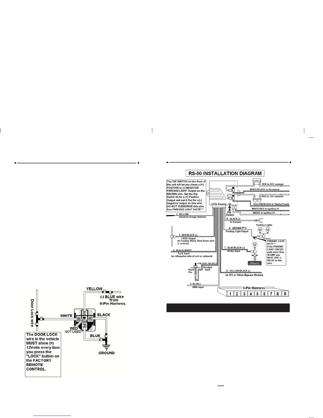
AUXILIARAUXILIARYY INPUT INPUT (-) BLUE (-) BLUE
(For your factory keyless or af(For your factory keyless or aftermarket alarm)termarket alarm)
When connecting this unit to a factory keyless entry system, you must locate
the door lock wire that tests as a positive when you press the lock button on
the factory remote. A relay Part #775 is required to change the positive output
from the door lock circuit to a negative for the BLUE
BLUE wire on the control module.
If the lock wire on the vehicle is negative when the lock button is pressed, no
relay is required. You can tie directly into the BLUE
BLUE wire on the 9-pin harness.
LOCATING & MAKING CONNECTIONS
13
CONNECTING THE 9-PIN HARNESS
IMPORTANT NOTICE: This unit when first powered up must be
initialized to code in the remote transmitter.
INITIALIZATION OF THE CONTROL MODULE:
When the unit is first powered up and all the connections are completed with
the harness plugged into the control module, the parking lights on the vehicle
will begin to flash.
You must press and hold the brake pedal then press any button on the
remote until the parking lights stop flashing. Then release the brake
and the button on the remote.
This procedure must be performed if the remote is lost or the unit memory
is cleared.
At any time you may test the remote starter. If the vehicle does not start,
check the following:
1. You may have an anti-theft system. Refer to the vehicle diagrams on the
web site or the listings on pages 17-19 in the manual.
2. The hood switch wire is grounded. Make sure the hood is shut and there
is no (-) ground to the BLACK/BLUE hood switch wire.
3. There is (+) positive voltage only when the brake is pressed.
4. The control module may need cleared. Follow the clearing procedure on
page 17 then re-initialize the control module.
TTACH INPUTACH INPUT (BLACK WITH WHITE STRIPE) (BLACK WITH WHITE STRIPE) (Optional)
By this time, you should have determined the way you want your vehicle to
start (tach or tachless). Tachless uses voltage electronic signals and timing to
work. Tach types use a signal directly from the ignition coil. If you have chosen
the TACHLESS start option, simply proceed to the next step and skip the
following instructions. Make sure you tape this wire up if not used. For TACH
mode connect the BLACK WITH WHITE STRIPEBLACK WITH WHITE STRIPE wire from the 9-pin harness
to the negative side of the coil or the tach wire at the coil pack under the hood.
To find the coil pack follow the spark plug wires back to their beginning point.
To operate in tach mode, make sure to program tach option. See programming
tach option page 15.
AUXILIARAUXILIARYY INPUT INPUT (BLUE) (For (BLUE) (For AfAftermarket termarket Alarms)Alarms)
If you use this starter with an aftermarket alarm, connect the BLUEBLUE wire from
the 9-pin harness to the second or third channel output of your existing alarm.
When the output is activated, a signal will activate the remote starter. NOTE:
This wire will also be used if you wish to connect the unit up to operate
off of your Factory Keyless Entry. See Programming to Start Your Vehicle
from your Factory Keyless Entry, page 15. (Extra part #775 relay is required.
See diagram, page 12.)
 Loading...