11
(Parking Light Output continued)
If the circuit is (+) positive and pulls less than 10 amps, connect the BROWN wire from
the 9-pin harness directly to the vehicles parking light wire. If the circuit is negative,
you must use a relay if not hooking to the BCM or the vehicles computer. Part #775
is required for most negative parking light circuits.
Connect the BROWN wire from the 9-pin harness to the vehicles parking light circuit
if you are not using a relay.
BRAKE INPUTBRAKE INPUT (BLUE WITH BLACK STRIPE) (BLUE WITH BLACK STRIPE)
The brake wire is located on the switch near and above the brake pedal, if you cannot
locate this wire at the brake switch, you will then need to locate a wire at the rear window
brake light or at the brake light system in the rear of the vehicle. The correct wire will
show +12V only when the brake is pressed. Connect the BLUE WITH BLACK STRIPEBLUE WITH BLACK STRIPE
from the 9-pin harness to this wire.
ANTENNAANTENNA (YELLOW) (YELLOW)
For best results, run the antenna (YELLOW WITH BLACK YELLOW WITH BLACK TIPTIP in the 9-pin harness)
as straight as possible. Do not place the antenna next to any metDo not place the antenna next to any metal pal partarts or the vehicles or the vehicless
main computer control.main computer control.
FFACTACTORORYY ALARM SHUTALARM SHUT DOWN WIRE (F DOWN WIRE (FASD) (-) (RED WITH BLACK STRIPE)ASD) (-) (RED WITH BLACK STRIPE)
If your vehicle is equipped with a factory alarm system (as most vehicles with
a factory keyless entry are) or, if your vehicle DOES NOT have a factory remote
control that honks the horn when locking and unlocking the doors, or when
you use the key in the drivers door, you DO NOT get a light on the dash that
says security then mostly you will not need to use this wire. If your vehicle
is so equipped, probe for a small gauge wire (usually found in the drivers side
kick panel) that shows (-) ground when the door lock cylinder is turned to the
unlock position using the key. This wire will usually show a (+) positive voltage
before turning the key. NOTENOTE: Some factory disarm wires remain neutral before
you turn the key to unlock instead of +12v positive. Connect the RED WITHRED WITH
BLACK STRIPEBLACK STRIPE wire from the 9-pin harness to this wire.
HOOD PIN SWITCH (BLACK WITH BLUE STRIPE)HOOD PIN SWITCH (BLACK WITH BLUE STRIPE)
This feature will keep the engine from starting, or shut off the engine when in
remote start mode only. The hood pin switch has no control over the engine
when started with the ignition key or under normal operation. Locate a good
chassis ground, if at all possible do not install the pin switch in the rain gutter.
Drill a 5/16 hole, insert the pin switch into the hole and tighten. Check for the
hood adjustment, there is approximately 1/4 adjustment in the pin switch.
Close the hood easy, making sure that the pin switch is not keeping the hood
from closing all the way, if it does, cut off approximately 1/8 of the black plastic
off of the top of the hoodpin switch and try closing the hood again. Check to
make sure that the hoodpin switch remains neutral when the hood is closed
and shows ground when the hood is open. Plug the BLACK WITH BLUEBLACK WITH BLUE
STRIPESTRIPE wire from the 9-pin harness into the bottom of the hood pin switch.
LOCATING & MAKING CONNECTIONS
14
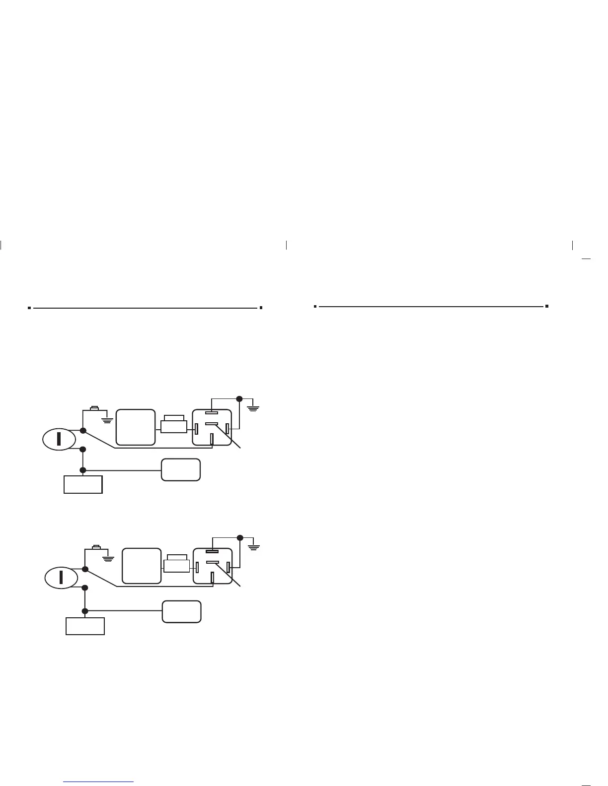
MECHANICALMECHANICAL NEUTRAL NEUTRAL SAFETY SAFETY SWITCH SWITCH
When installing a remote starter on GM vehicles or Dodge Dakotas built prior to
1996, you must:
Use the diagram below to create a circuit that will prevent the Use the diagram below to create a circuit that will prevent the remote stremote starter fromarter from
ststarting the vehicle unless the key is removed from the ignition sarting the vehicle unless the key is removed from the ignition switch.witch.
NEUTRAL SAFETY SWITCH
PRE-1996 DODGE DAKOTPRE-1996 DODGE DAKOTASAS
Optional pOptional part #775 requiredart #775 required.
Ground
Ground
DO NOTDO NOT USE RED WIRE, USE RED WIRE, TTAPE OFFAPE OFF
86
30
87a
87
85
5 Amp
fuse
Tie into heavy
white wire on
4-relay harness
(-) Negative
hood pin wire
Message center
or key buzzer
Drivers Door Switch
Key
Cylinder
BLACK/LBLACK/LTT. BLUE. BLUE
LLTT.BLUE/GREEN.BLUE/GREEN
BLACKBLACK
YELLOWYELLOW
BLUEBLUE
WHITEWHITE
REDRED
FUSE
PRE-1996 GM REAR-WHEELPRE-1996 GM REAR-WHEEL DRIVES WITH PURPLE CRANK WIRE DRIVES WITH PURPLE CRANK WIRE
Optional pOptional part #775 requiredart #775 required.
Ground
Ground
86
30
87a
87
85
5 Amp
fuse
Tie into heavy
white wire on
4-relay harness
(-) Negative
hood pin wire
Message center
or key buzzer
Drivers Door Switch
Key
Cylinder
TTANAN
GREENGREEN
BLACKBLACK
YELLOWYELLOW
BLUEBLUE
WHITEWHITE
DO NOTDO NOT USE RED WIRE, USE RED WIRE, TTAPE OFFAPE OFF
REDRED
FUSE
Caution: Please check the position of the switch before the wire connection
is made. You may cause damage to the control module if the switch is in
the incorrect position.
The switch is located between the 9-pin harness and the ignition #1 terminal. The
switch towards the inside of the control module is the (+) positive setting and
towards the outside of the control module is the (-) negative setting.
Probe your vehicles parking light wire. If the test light shows (+) positive or glows
RED only when the parking lights are turned to the on position, the circuit is (+)
positive. (Move the switch to the in position.)
If the test light shows a (-) negative or glows GREEN only when the parking
lights are turned to the on position, the circuit is (-) negative. (Move the switch
to the out position.)
The parking light output from the control module is rated at 10 amps max and is
suitable for most vehicles. If there are additional lights and devices added to the
vehicles parking light circuit, check the power draw with a volt meter. A relay is
required if the vehicles parking lights draw more than 10 amps. (Part #775) See
diagram.
 Loading...