10
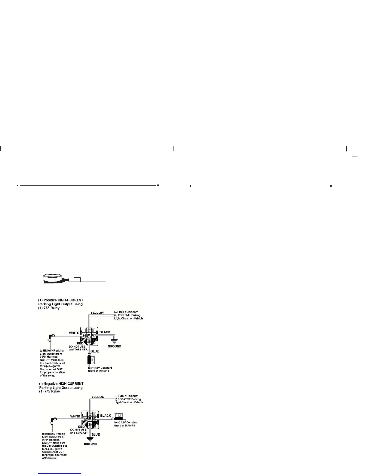
PPARKING LIGHTARKING LIGHT OUTPUT OUTPUT (+/-) (BROWN) (+/-) (BROWN) (Optional Part #775 may be required)
LOCATING & MAKING CONNECTIONS
Note: Remove any paint below the
spade connector.
Factory Bolt
Spade Connector
Black Ground Wire
CHASSIS GROUND (BLACK)CHASSIS GROUND (BLACK)
Locate an easy to get to bolt or screw located under the drivers side of the dash
and attach the BLACK
BLACK ground wire from the 9-pin harness securely as pictured.
15
OPERATOR PROGRAMMING
ADDING ADDING ADDITIONALADDITIONAL REMOTES USING REMOTES USING AA WORKING REMOTE WORKING REMOTE
Press and hold the brake, press and hold Button #1 on the working remote
for approx. 5 seconds or until the parking lights flash (1) one time, release
button #1 on this remote and press and any button on the NEW remote,
the parking lights will flash (3) three times, the new remote is now
programmed.
ADDING ADDING ADDITIONALADDITIONAL REMOTES WITHOUT REMOTES WITHOUT AA WORKING REMOTE WORKING REMOTE
You must first follow the procedure for clearing the memory on page 16
then proceed with the initialization procedure on page 13.
TTach/Tach/Tachless Optionachless Option
Press and Hold the BRAKE, with the brake held, press and hold button
#2 until the parking lights flash (2) two times, release button #2 and press
and release button #1 the parking lights will flash (1) once. The unit is
now programmed for TACH mode. If you press and release button #1
again and the parking lights flash (2) two times, the unit is programmed
for TACHLESS mode, release the brake and the parking lights will flash
(3) three times.
Note: The factory default setting is TACHLESS mode.
Programming TProgramming Tach Learnach Learn
Press and hold the brake, with the brake held, press and hold button #2
until the parking lights flash (2) two times, release button #2, then press
and release buttons #1 and #2 at the same time and the parking lights
will flash (2) two times, while still holding the brake, start the vehicle with
the ignition key. With the vehicle running, press Buttons #1 and #2, the
parking lights will flash (1) one time signifying the tach learn mode is
entered. Release Buttons #1 and #2 and in approximately 5 seconds the
parking lights will flash (3) three times, the tach signal is now learned.
Turn off the ignition key and release the brake.
Note**** The unit must be programmed for TACH mode before the
TACH LEARN function will program.
Programming to SProgramming to Sttart your Vart your Vehicle with your Factory Keyless Entryehicle with your Factory Keyless Entry
Press and hold the brake, then press and hold Button #2 on the remote transmitter
until the parking lights flash once (if hooked up) or for approximately six seconds
or until the unit clicks or flashes one time. Then press Button #2 again, the parking
lights will flash (1) time. If they flash twice, press Button #2 again until the parking
lights flash once. The unit is now in the factory keyless mode. NOTE:
NOTE: AA relay is relay is
required for this feature if the lock wire on the vehicle is a (required for this feature if the lock wire on the vehicle is a (+) positive output.+) positive output.
Programming for Programming for AfAftermarket termarket Alarm SAlarm Sttartingarting
Press and hold the brake, press and hold Button #2 on the remote transmitter
until the parking lights flash one time (if hooked up) or for approximately six
seconds until the unit clicks or flashes one time. Then press Button #2 again, the
parking lights will flash (1) time. If they flash twice, press Button #2 again until the
parking lights flash once. The unit is now in the factory keyless mode. NOTE: A
relay is required for this feature if the lock wire on the vehicle is a (+) positive
output.
Auxiliary InputAuxiliary Input
(For your factory keyless or af(For your factory keyless or aftermarket alarm)termarket alarm)
When connecting this unit to a factory keyless entry system, you must locate the
door lock wire that tests as a positive when you press the lock button on the factory
remote. A relay Part #775 will be needed to convert the positive output from the
door lock to a negative pulse for the BLUE wire on the 9-pin harness. If the wire
is negative when you press the lock button on the factory remote, you can tie
directly into the BLUEBLUE wire. This wire is usually located in the drivers kick panel,
in the harness that is coming from the drivers door.
not use the Ignition #2 heavy gauge WHITE WITH RED STRIPEWHITE WITH RED STRIPE wire (if your vehicle
does not have an Ignition #2 wire) you can take that WHITE WITH RED STRIPE
WHITE WITH RED STRIPE
wire and attach it to the Accessory #2 wire, this way you do not have to tie both the
Accessory #1 wire and the Accessory #2 wires together on the WHITE WITH BLACK
WHITE WITH BLACK
STRIPESTRIPE wire from the main module.
ST
STARARTTER/CRANK WER/CRANK WIRIRE (YELLOW WITH BLACK STRIPE) (+12V in the stE (YELLOW WITH BLACK STRIPE) (+12V in the start position only)art position only)
Make all connections as close to the ignition switch as possibleMake all connections as close to the ignition switch as possible..
The starter/crank wire is also in the main harness. Check your chart for probable colors and
verify the wire
. The correct wire(s) will show +12V and the RED light will glow bright
onlyonly in the crankcrank position. This wire will not show +12V in any other position. Attach the
YELLOW WITH BLACK STRIPE
YELLOW WITH BLACK STRIPE wire to it. NOTE: Some vehicles use two (2) starter/crank
wires (mostly Nissans and Audis). In this case, connect both wires from the ignition switch
harness to the YELLOW WITH BLACK STRIPE
YELLOW WITH BLACK STRIPE wires from the main module.
 Loading...