9
IGNITION WIGNITION WIRIRE(S) (WHITE) and (WHITE WITH RED STRIPE) (+12V in run, crankE(S) (WHITE) and (WHITE WITH RED STRIPE) (+12V in run, crank
and sometimes accessory)and sometimes accessory)
Make all connections as close to the ignition switch as possibleMake all connections as close to the ignition switch as possible..
The ignition wire(s) are also located in the main harness coming from the ignition
switch. Check your chart for probable colors and probe each wire with your provided
test probe. The correct ignition wire(s) will show +12V and the RED light will glow
bright when the ignition switch is in the RUN, CR
RUN, CRANK ANK and sometimes in the
ACCESSOR
ACCESSORYY (newer GMs) position. The correct wires will not show +12V when
in the OF
OFFF or AACCESSORCCESSORYY position (other than some GMs).
1. If your vehicle has only one (1) ignition wire connect the heavy gauge
WHITE
WHITE wire to the Ignition #1 wire in the Ignition Switch Harness.
2. If your vehicle has (2) ignition wires, connect the WHITE
WHITE wire as stated
in step 1, to Ignition #1, then connect the heavy gauge WHITE WITHWHITE WITH
RED STRIPERED STRIPE wire to the Ignition #2 wire in the Ignition Switch Harness.
3. If your vehicle has (3) Ignition wires connect the heavy gauge WHITEWHITE
wire to the Ignition #1 wire and Ignition #3 wire in the Ignition Switch
Harness. Make sure you connect the WHITE WITH RED STRIPE wire to
the Ignition #2 wire as stated in Step 2.
ACCESSORACCESSORYY WIRE(S) WIRE(S) THATHATT POWER POWER THE HEATHE HEATER/BLOWER MOTTER/BLOWER MOTOR (WHITE WITHOR (WHITE WITH
BLACK STRIPE) (+12V in run or on positions). BLACK STRIPE) (+12V in run or on positions). This wire is also in the main ignition switchThis wire is also in the main ignition switch
harnessharness. Make this connection as close to the ignition switch as possib. Make this connection as close to the ignition switch as possible.le.
Most vehicles will have one (1) accessory wire; however somesome Fords, newer GM vehicles
and Chrysler 94 and up will have two (2) or more accessory wires. Check your wire color
chart and then verify these wire(s).
The correct wire(s) will show +12V and the RED
light will glow bright
when the ignition switch is in the ACCACC or RUN RUN or positions, but never
OFF
OFF or CRANKCRANK.
1. If your vehicle has only one (1) accessory wire connect the heavy gauge WHITE WITH
WHITE WITH
BLACK STRIPEBLACK STRIPE wire to this wire.
2. If your vehicle has two (2) accessory wires (some GMs and most Fords), connect the
WHITE WITH BLACK STRIPE
WHITE WITH BLACK STRIPE wire to both accessory wires. In some cases, if you did
LOCATING & MAKING CONNECTIONS
16
OPERATOR PROGRAMMING
RUNTIME CONFIRMARUNTIME CONFIRMATION:TION:
With the vehicle not running press and release Button #2, the parking
lights will flash (1) one time for each 5 minutes of programmed run time.
Example: (2) two flashes = 10 minutes
TTO SETO SET THE RUNTIMETHE RUNTIME
:
Press and hold Button #2 on the remote control for approx. 10 seconds
or until the parking lights begin to flash (one flash for each 5 minutes of
runtime) and when Button #2 is released the new runtime is programmed.
To check this programmed runtime for example, press and release Button
#2 if the parking lights flash (3) three times, the unit is programmed to run
for 15 minutes.
CCLEARING LEARING THE UNITS MEMORTHE UNITS MEMORYY::
Press and hold the brake, with the brake held, cycle the key in the ignition
switch from OFF to RUN, (5) five times within 4 seconds, the parking lights
will flash (3) three times. Unplug the unit from ALL wires and harnesses,
wait 30 seconds, plug the unit back into all harnesses, the units memory
is now cleared, set back to factory settings and ready to learn a remote.
You must follow the initialization procedure on page 13 to reprogram the
transmitter.
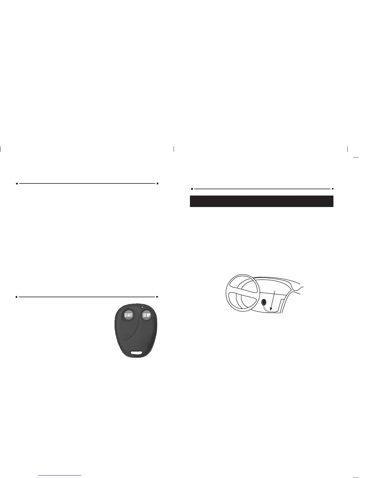
HOW TO USE YOUR NEW REMOTE
SSttartart
Press and release Button #1 the vehicle will remote
start.
S
Stoptop
Press and release Button #2 the vehicle will shut
down.
Pit S
Pit Stop: Exiting the Vtop: Exiting the Vehicle with the Engineehicle with the Engine
RunningRunning
Make sure the transmission is in park
and the brake is not pressed then
press and release Button #1 (start)
before turning the ignition switch off.
(The engine will remain running for
15 minutes or until the brake is pressed).
SSttartart
Using the remote included in this kit:Using the remote included in this kit: Press and release Button #1.
Using your factory keyless entry remote:Using your factory keyless entry remote: Press the Lock button (3) times.
Using Using AfAftermarket termarket Alarm:Alarm: Press the second channel button on your remote transmitter.
SStoptop
Using the remote included in this kit: Using the remote included in this kit: Press Button #2.
Using your factory keyless entry remote:Using your factory keyless entry remote: Press the Lock button (3) times again.
Using Using AfAftermarket termarket Alarm:Alarm: Press and release the second channel button on your remote
transmitter.
Pit SPit Stop (Exiting the Vtop (Exiting the Vehicle with the Engine Running)ehicle with the Engine Running)
With your factory keyless remote:With your factory keyless remote:
If the vehicle is running with the ignition key, pressing the Lock button on the factory keyless
will cause the parking lights to flash once (if connected). You can now turn off your ignition
key, remove the key and exit the vehicle. The vehicle will remain running for 15 minutes.
NOTE: Some vehicleNOTE: Some vehicles factory keyless wont work if the engine is running. If your vs factory keyless wont work if the engine is running. If your vehicleehicle
operates in this fashion, pit stop will not function.operates in this fashion, pit stop will not function.
For wiring charts please visit our website, www.alertautomotive.com.
Most of the wires you will be using will be in a tMost of the wires you will be using will be in a taped or nylon sleeve comingaped or nylon sleeve coming
from the ignition switch. from the ignition switch. YYou must find and remove about six inches of thisou must find and remove about six inches of this
outer covering for testing and connecting.outer covering for testing and connecting.
CONSTCONSTANTANT POWER (RED) POWER (RED) (+12V(+12V, key in any position including of, key in any position including off)f)
Make all connections as close to the ignition switch as possibleMake all connections as close to the ignition switch as possible..
These wire(s) are in your vehicles main ignition harness, usually located in the
steering column coming from the ignition switch. Probe each wire with your
provided test probe. The correct wire(s) will show +12V and the RED light will
glow bright on the test probe when the ignition switch is in these 5 positions5 positions
(ACC-LOCK-OFF-RUN-CRANK)(ACC-LOCK-OFF-RUN-CRANK).
1. If your vehicle has only (1) constant power wire, attach
both heavy gauge REDRED wires to it.
2. If your vehicle has (2) constant power wires, attach one REDRED wire to each.
IGNITION HARNESSIGNITION HARNESS
UNDER DASHUNDER DASH
 Loading...