INSTALLATION AND OPERATIONS GUIDE
® U.S. Registered Trademark
Copyright © 2024 Honeywell Inc. • All Rights Reserved
31-00531-01
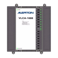
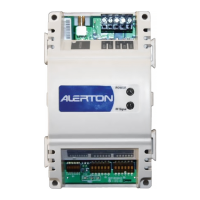
VAV IP Controller
General ................................................................................... 3
Trademark Information .......................................................... 3
Product Description ................................................................ 3
Controller Part Numbers....................................................... 3
Dimensions................................................................................. 4
Network Security ................................................................. 5
General Safety Information and Installation
Precaution ............................................................................. 5
Read all the instructions below........................................... 5
High Voltage safety test......................................................... 5
Lightning and high-voltage danger ................................. 5
Wiring and equipment separations .................................. 5
Specifications ....................................................................... 6
Electrical ...................................................................................... 6
Operational Environment ..................................................... 6
Hardware ..................................................................................... 6
Integrated Actuator ................................................................ 6
Weight And Dimensions ........................................................ 6
Communications...................................................................... 7
Air Flow Sensor.......................................................................... 7
Universal IO ................................................................................ 7
Solid State Relay (SSR) .......................................................... 7
Hardware overview.............................................................. 8
IP Model ....................................................................................... 8
Service Button ........................................................................... 8
Factory Reset Using the Service Button .................. 8
Mounting................................................................................ 9
Before Mounting Actuator.................................................... 9
Mounting Actuator onto Damper Shaft .......................... 9
Tools Required.................................................................... 10
Damper Position Feedback .................................................. 11
Raw Value ............................................................................. 11
Input Scaling....................................................................... 11
Input Scaling the damper position
feedback ...................................................................................... 11
Airflow Sensor Connection................................................... 13
Differential Pressure Installation
Recommendations................................................................... 13
Airflow Sensor Replacement................................................ 13
Power Supply ........................................................................ 15
General Information................................................................ 15
Power Wiring .............................................................................. 15
Power supply guidelines and requirements .................. 15
Power ratings ............................................................................. 15
Selecting a transformer ......................................................... 16
Power supply grounding and wiring................................. 16
Input / Output Wiring......................................................... 17
Wiring Requirements.............................................................. 17
Internal Wiring Examples...................................................... 17
Internal Wiring.................................................................... 17
Indentifying terminals and terminal wire ....................... 18
Power supply terminals................................................... 18
Grounded terminals......................................................... 18
Common terminals........................................................... 18
Universal inputs and outputs terminals .................. 18
20 VDC Source ................................................................... 18
Terminal Connections ............................................................ 19
UIO Wiring................................................................................... 20
Universal inputs................................................................. 20
Pulse-type inputs.............................................................. 21
Analog outputs (AOs) ...................................................... 21
Binary Outputs (BOs) ...................................................... 22
SSR Wiring .................................................................................. 22
SSR wiring with one transformer and factory
jumper.......................................................................................... 22
SSR wiring with separate transformer without
factory jumper........................................................................... 22
Microset Bus ......................................................................... 23
Microtouch ................................................................................. 23
Microset II ................................................................................... 23
Microset 4 ................................................................................... 23
Wire shields and shield grounding ................................... 23
MS4 / Microtouch Wiring Examples................................ 24
LED Operations .................................................................... 26
BACnet and Modbus (Future release) LED Status ..... 26
Controller LED Status ............................................................ 27
BACnet IP Controller........................................................... 28
IP Configuration ....................................................................... 28
Static IP Configuration .......................................................... 28
Connect to a IP Network........................................................ 28
VAV IP Configuration .......................................................... 29
Compass Device Configuration.......................................... 29
Recovering from a Misconfiguration ............................... 29
Initial Screen .............................................................................. 29
Ethernet and IP......................................................................... 30
BACnet Configuration ............................................................ 32
BACnet Point Objects ............................................................. 34
BACnet Network Configuration.......................................... 35
BACnet/IPv4 ....................................................................... 36
BACnet/IPv6 ....................................................................... 37
BACnet Compatibility ............................................................. 39
Time Synchronization Configuration............................... 40
UTC Offset, Daylight saving, Latitude, Longitude ...... 41
Configuring all Inputs and Outputs (Templates) ........ 43
Inputs............................................................................................ 46
Device Units ........................................................................ 46
Microset Detection Mode .............................................. 46
Hardware Input Mode ..................................................... 47
Data Presentation Mode ................................................ 48
Pulse Value .......................................................................... 49
Pulse Time Base................................................................. 49
Input Scaling....................................................................... 50
Object Units......................................................................... 51
Outputs ........................................................................................ 52
Hardware Mode.................................................................. 52
Output Scaling ................................................................... 52
Out of Service (For Inputs and Outputs).................. 52
Binary Outputs................................................................... 54