Alesis D4/D5 Drum Modules Service Manual 1 02/19/03
1.00 General Descriptions
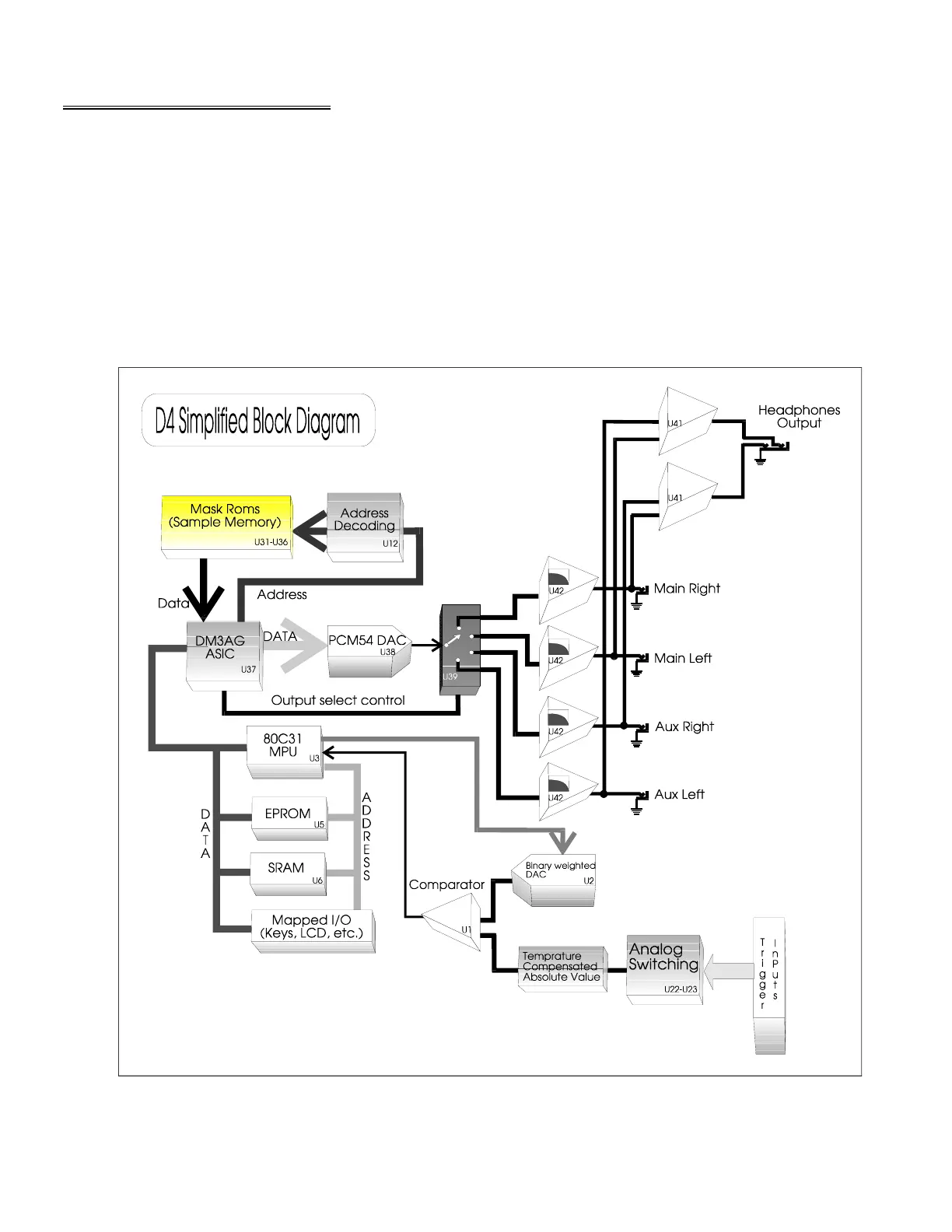
The D4 is a rather simple unit to repair, as the component count has been greatly reduced by
the use of the DM3AG ASIC (Application Specific Integrated Circuit). The basic building blocks of the
unit are the 8031 micro controller (which handles all basic unit functions such as triggers , LCD output,
Keypad input, and MIDI I/O), sample generation circuits (ASIC, DAC, Analog switch, and output
filter/buffers), and some miscellaneous support circuits such as system reset, battery backup, etc.
The DM5 (Alesis product code D5) is extremely similar in design, with the one major difference
being the use of better DACs. This has required the addition of on extra IC {D56IFT ASIC} for the
purpose of converting parallel data to a serial format and generating clock signals for use with the new
DACs. In addition this IC consolidates several other functions previously performed by discreet logic
such as memory map decoding and handling the highest order Mask ROM addressing lines. Please
note that there are several main PC Board revisions, and some differences will be noticed from unit to
unit. Reference designators refer to the D4 unless in brackets {D5 reference} or otherwise noted.
Diagram 1
 Loading...