EngliSh
EngliSh
BAttERY INstALLAtION
Insert 2 AA batteries according to the polarity as
shown in Fig. 5.
INtRODUctION:
Electronics is the eld of manipulating electrical
currents and voltages using passive and active
components that are connected together to create
circuits. Electronic circuits range from a simple
load resistor that converts a current to a voltage, to
computer central-processing units (CPUs) that can
contain more than a million transistors.
WhAt DOEs It DO?
This electronic motion sensor triggers an alarm
when something moves in front of the motion
sensor.
hOW DOEs It WORK?
The two AA batteries are wired in series to provide
3V of power to the integrated circuit board on which
a micro-controller constantly monitors the signal
from the light sensor. When the micro-controller
detects a sudden change in light level, such as
when you wave your hand in front of the sensor,
it turns on the alarm. Due to the electro-optical
property of the light sensor, it works best in bright
environments and needs a big change in the light
level to trigger the alarm. If the colour or brightness
of the moving object is similar to the background, it
may not be detected.
FAct FILEs:
Motion sensors are widely used in access control
such as automatic door, greeting message player
and security alarm. Recently it is also integrated
into video game controllers to sense the movement
of the players. The simple one like the one you just
built use visible light for detection while more
advanced devices use passive infrared (PIR) to
detect the movement of people or use infrared
transmitters and receivers to detect movement.
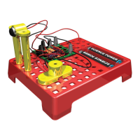
cOmPONENts
1. 1 x Base plate
2. 1 x Micro controller board
3. 1 x Buzzer
4. 1 x Photo Sensor with holder
5. 2 x Sensor stand
6. 6 x Spring connector
Batteries required: 2 X AA (not included)
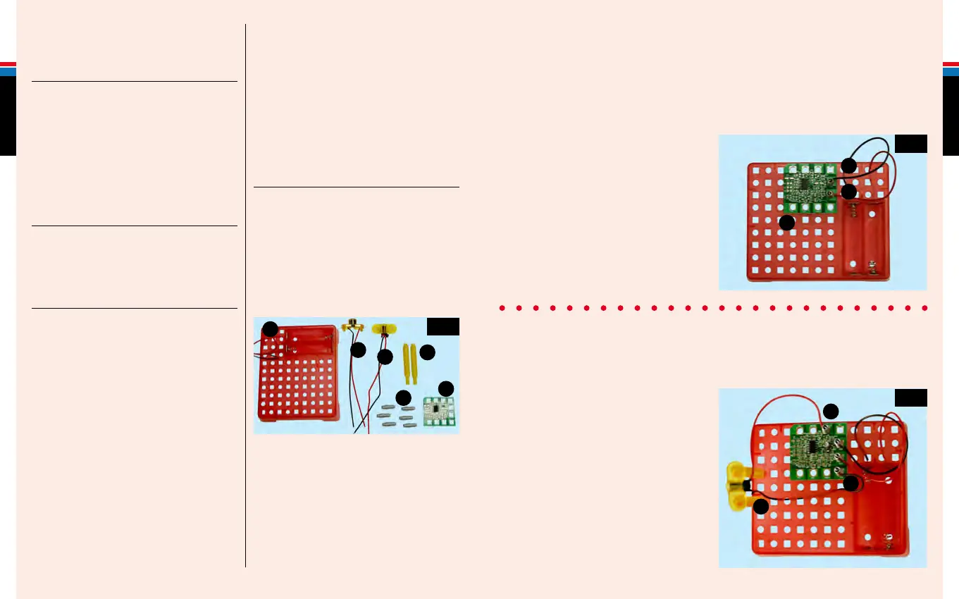
1. Place the Micro controller board (2) on the base plate (1). Install two spring connectors (6) into the holes
(VSS1,VCC1) by pushing the narrow end down, as far as they will go, as shown in Fig. 2. Connect the red and
black battery wires to the corresponding spring connectors by bending the spring over to create a gap into
which the metal wire is inserted, as shown:
Place the Micro controller board -1
Connect the battery black wire – 2
Connect the battery red wire – 3
AssEmBLING YOUR ELEctRONIc
mOtION sENsOR
Fig. 1
2. Install the photo transistor (4) with sensor stand (5) on the base plate. Insert two spring connectors and
connect the photo transistor wires to holes (3) and (4) as shown in Fig. 3:
Assembly the stand with photo sensor and place on the base plate -4
Connect the sensor red wire –5
Connect the sensor black wire –6
Fig. 2
Fig. 3
1
1
2
2
5
5
6
6
3
3
4
4
 Loading...