EasyManua.ls Logo

Algo 3006 User Manual

Algo 3006
4 pages
To Next Page IconTo Next Page
Page #1 background imageLoading...
Page #1 background image
Algo Communication Products Ltd. 4500 Beedie Street, Burnaby, B.C. Canada V5J 5L2
Tel: (604) 438-3333 Fax: (604) 437-5726 www.algosolutions.com
Algo Communication Products Ltd. 4500 Beedie Street, Burnaby, B.C. Canada V5J 5L2
Tel: (604) 438-3333 Fax: (604) 437-5726 www.algosolutions.com
P. 1
ABOUT THE 3006 DOORPHONE
The Algo Doorphone Model 3006 consists of a control unit (3005), a door station
(3004) and a power supply (3242). All options and controls are factory set to allow
for a quick installation of simple wire connections.
QUICK INSTALL
STEP 1
Run a two-pair cable from the door station location to the control unit location
(equipment room). A recessed double-gang utility box is ideal for mounting the
door station. The door station can be located anywhere a speakerphone or talkback
paging would be considered. The door station should be mounted at shoulder
height.
STEP 2
Connect the door station as per the wiring diagram on page 4. Use this wiring
configuration as a standard so that all installations are similar. Mount the door
station, dressing all wires neatly.
STEP 3
Wall mount the control unit as near as possible to an AC outlet. Connect the door
station wires as per the attached drawing.
STEP 4
Connect the control unit terminals (T & R) to a CO line or trunk circuit of the
telephone system. The control unit will also work with single line telephones.
STEP 5
Connect the power adapter into the rear of the circuit unit cabinet and plug into an
AC outlet.
STEP 6
Test the unit by pushing the call button of the door station. The control unit initiates
ringing into the telephone system. Answer the “call” and ensure that a voice path is
established with the door station.
NOTE: The Doorphone is factory set to ring five times and then abandon the
call. This may be changed by setting the “ring persist” option switches.
3006 Trunk Port Doorphone Installation Guide
DC300600-05
Jul 02, 2002.
P.4
Question and Answer IconNeed help?

Do you have a question about the Algo 3006 and is the answer not in the manual?

Algo 3006 Specifications

General IconGeneral
BrandAlgo
Model3006
CategoryIntercom System
LanguageEnglish

Summary

3006 Trunk Port Doorphone Installation Guide

About the 3006 Doorphone

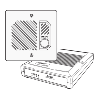
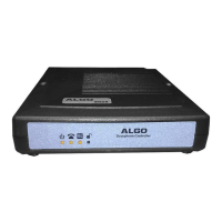
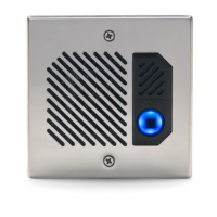
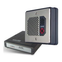
Details the components of the Algo Doorphone Model 3006, including control unit, door station, and power supply.

Quick Install Procedure

Provides a step-by-step guide for the rapid installation of the doorphone system.

Switch Options and Control

Ring Cadence Configuration

Configures the pattern and duration of the doorphone's ring signal using Switch-1.

Ring Persistence Settings

Sets the number of ring cycles before a call is abandoned, controlled by Switch-2.

Ring Enable/Disable Function

Controls ring voltage output at T&R via Switch-2 position 8, or operates auxiliary relay.

Speaker Volume Adjustment

Adjusts the audio output level using a knob on the rear of the control unit.

Microphone Sensitivity Adjustment

Adjusts microphone bias with a screwdriver for optimal switching function.

Relay Terminals Usage

Allows connection of an auxiliary ringer, following ring cadence and persist settings.

Auxiliary Jack Purpose

Provides power/signal for Algo Model 3106 Door Control Module; do not use for other purposes.

Repairs and Support

Field Repair Policy

Discourages field repair; requires return to Algo with standard procedures and an authorization number.

Customer Service Contact

Provides contact information for obtaining return authorization and additional product information.

Related product manuals