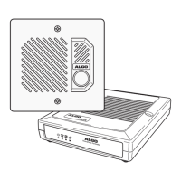
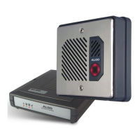
About the 3026 Doorphone
The 3026 Doorphone is a system comprised of a 3004 Door Station and 3025 Control Unit. This
guide applies to the installation of the 3025 Control Unit with a 3004 Door Station.
The 3026 Doorphone provides intercom capability for a telephone system through a spare trunk
port. The Doorphone emulates a telephone line by providing talk battery and ringing. Calls are
made by pressing the call button at the door station which causes the control unit to initiate
ringing to the trunk port. Anytime that the trunk port is off-hook, communication is provided
hands-free at the door station.
Installation
The 3026 Doorphone is shipped with the option switches and controls preset for optimum
performance and most common configuration. We suggest that the Doorphone be installed and
tested with these settings prior to any adjustments.
Wiring Requirements
Prewire at least one pair of 24 AWG twisted wire between the control unit location and
telephone system. The control unit must be installed in a dry protected environment (usually
beside the telephone system). The maximum distance between the control unit and telephone
system is 1000 meters or 3200 feet.
Prewire at least two pair of 24 AWG twisted wire between the control unit and door station. The
door station may be mounted outdoors in un-protected areas. Maximum distance is 300 meters
or 1000 feet.
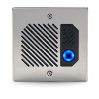
Mounting
Install the door station into a recessed or surface mounted double-gang electrical box of the type
that would be used for two light switches or two duplex receptacles. A sealant should be used
behind the door station to prevent water from penetrating behind the door station. The door station
can be used outdoors in ambient temperatures -30 degC to +40degC (-22degF to +104degF).
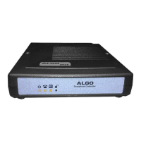
The control unit is wall mounted within 1.5m (5ft) of a 120 volt 60 Hz AC receptacle for the
supplied 3242 external plug-in adapter.
Wire Connections
The door station connects to the control unit terminals 1-4. The numbers are identified on both the
door station and control unit.
The terminals marked T and R (tip and ring) connect to the telephone system trunk port. A
modular jack (TEL) is also provided on the rear of the control unit.
The remaining terminals (C, NC, NO) are for door or gate control and are explained in the section
Door Control.
3026 Doorphone
Installation Guide
P.4
DC3026CI-02
AUGUST 28, 2000
Algo Communication Products Ltd. 4500 Beedie Street, Burnaby, B.C. Canada V5J 5L2
Tel: (604) 438-3333 Fax: (604) 437-5726 http://www.algo.ca
Algo Communication Products Ltd. 4500 Beedie Street, Burnaby, B.C. Canada V5J 5L2
Tel: (604) 438-3333 Fax: (604) 437-5726 http://www.algo.ca
P. 1