Do you have a question about the Alinco DR-635 and is the answer not in the manual?
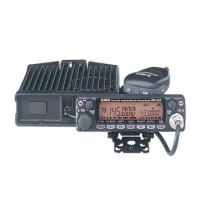
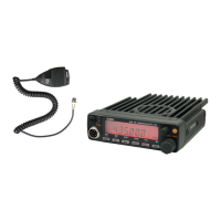
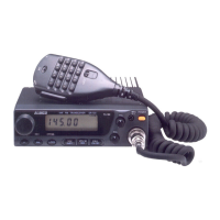
General specifications of the DR-635T/E radio.
Transmitter output power, modulation, and distortion specs.
Receiver sensitivity, circuitry, and selectivity specifications.
Detailed description of the VHF signal reception path.
Detailed description of the UHF signal reception path.
Detailed description of the FM signal reception path.
Description of VHF-VHF dual band reception.
Description of UHF-UHF dual band reception.
Explanation of VHF squelch control mechanism.
Explanation of UHF squelch control mechanism.
General transmit signal path from microphone to output.
Detailed path of VHF transmit signal.
Detailed path of UHF transmit signal.
Automatic Power Control circuit for VHF transmit.
Automatic Power Control circuit for UHF transmit.
Push-To-Talk circuit for VHF transmission.
Push-To-Talk circuit for UHF transmission.
Phase-Locked Loop circuit for VHF frequency control.
Phase-Locked Loop circuit for UHF frequency control.
Circuitry for powering on the device.
Dual Low Noise Operational Amplifiers pinout and description.
5V Voltage Regulator pinout and description.
8V Voltage Regulator pinout and description.
Bilateral Switch pinout and diagram.
10V Voltage Regulator test circuit and pinout.
Analog Multiplexer/Demultiplexer logic diagram and truth table.
Operational Amplifiers pinout.
Multiplexer/Demultiplexer function table and pinout.
Low Power FM IF block diagram.
5W Audio Power Amplifiers test circuit and pinout.
Quad Single Supply Operational Amplifier pinout.
Quad Single Supply Operational Amplifier pinout.
Voltage Detector pinout and test circuit.
Main CPU pin assignment and block diagram.
EE-P ROM block diagram and pin assignment.
LCD Driver pinout and block diagram.
2ch Electronic Volume pinout.
Front CPU pinout.
Detailed pin functions for the Front CPU.
Dual PLL Synthesizer parameter table and circuit.
Voltage Regulator pinout and diagram.
Voltage Regulator pinout.
Main CPU pinout and diagram.
Detailed pin functions for the Main CPU.
Visual outlines and part numbers for transistors, diodes, LEDs.
Nch MOS FET electrical characteristics and ratings.
Segment and common pin connections for the LCD.
Detailed pin assignments for LCD common signals.
Exploded view of the front panel components.
Exploded view of the bottom panel components.
List of parts for the front unit.
List of parts for the LED unit.
List of parts for the main unit.
List of mechanical components.
List of packing materials.
List of accessory screws and sets.
Key parameters and conditions for adjustment.
Table of adjustment settings and procedures.
Detailed test standards and adjustment methods for VHF.
Detailed test standards and adjustment methods for UHF.
Specifications and test standards for VHF performance.
Specifications and test standards for UHF performance.
Component layout of the front PCB, side A.
Component layout of the front PCB, side B.
Component layout of the main PCB, side A.
Component layout of the main PCB, side B.