EasyManua.ls Logo

Alinco DX-R8E - User Manual

Alinco DX-R8E
65 pages
Print Icon
To Next Page IconTo Next Page
Loading...
COMMUNICATIONS RECEIVER
DX-R8T/E
Instruction Manual
Thank you for purchasing your new ALINCO receiver.
This instruction manual (and addendum sheets) contains important safety and operating
instructions.
Please read this manual carefully before using the product and keep it for future reference.
PS0633 DX-R8T/E

Table of Contents

Questions and Answers

  • A
    anorrisAug 12, 2025
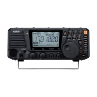
    Why Alinco DX-R8E power does not come on?
    • T
      Taylor Castillo DDSAug 12, 2025
      There are several reasons why your Alinco Receiver might not be powering on. It could be due to: 1. An incorrectly connected DC power cable – ensure it is properly connected. 2. A blown fuse – replace the fuse. 3. Wrong plug polarity – correct the polarity and replace the fuse. 4. The DC regulated power supply switch being off – turn the power switch on. 5. Insufficient voltage from the power supply – ensure a regulated 13.8 V DC ± 15 % power supply is used and adjust the operating voltage within the range of 11.7 to 15.8 V DC.
  • V
    Virginia KimAug 16, 2025
    What to do if there is no sound from the Alinco Receiver speaker?
    • A
      Alejandra GutierrezAug 16, 2025
      If you're not getting any sound from your Alinco Receiver speaker, consider these possible causes: 1. The AF control knob might be turned fully counterclockwise. Rotate the AF control knob to adjust the volume. 2. The external speaker cable may be short-circuited or damaged. Check the cable. 3. Headphones or earphones might be plugged into the speaker jack. Unplug them. 4. The squelch level might be set too high. Turn the SQL control knob counterclockwise to unmute the squelch.
  • W
    William WilsonAug 19, 2025
    Why Alinco DX-R8E Receiver only receives strong signals?
    • A
      Andrew MartinAug 19, 2025
      If your Alinco Receiver is only picking up strong signals, it could be due to: 1. A muted squelch. Turn the SQL control knob counterclockwise. 2. The ATT being activated. Press the [RF] key to turn ATT off. 3. A defective antenna, short-circuited, or damaged coaxial cable. Check the antenna, cable, and connector. 4. An antenna that is not suitable for the receiving band. Connect the correct antenna.
  • F
    fwardAug 25, 2025
    What to do if Alinco Receiver received signal is not demodulated?
    • F
      Frank TurnerAug 25, 2025
      If the received signal on your Alinco Receiver is not being demodulated: 1. Check that the correct mode is selected. If using SSB, verify LSB and USB settings. 2. Ensure the correct passband is set. Adjust the IF control knob until proper audio is heard and select the appropriate filter.
  • E
    Emma ContrerasAug 27, 2025
    How to unlock Alinco Receiver tuning dial?
    • W
      Wendy BlairAug 27, 2025
      If the frequency isn't changing when you rotate the main tuning dial on your Alinco Receiver, the dial might be locked. Press the [ ] key to unlock it.
  • B
    Brandon MosleyAug 31, 2025
    Why Alinco DX-R8E Receiver scan does not start?
    • C
      Carmen GrimesAug 31, 2025
      If the scan function isn't starting on your Alinco Receiver, it may be because the scan setting is incorrect in the Set mode, or the squelch is unmuted. Correct the scan type or mute the squelch.
  • M
    Mrs. Laura BryantSep 4, 2025
    Why Alinco DX-R8E memory scan will not start?
    • R
      Richard DavisSep 4, 2025
      If the memory scan won't start on your Alinco Receiver, the memory channel might be unprogrammed. Program a memory channel.
  • C
    Chase MorrisSep 7, 2025
    Why Alinco Receiver memory frequency cannot be changed?
    • D
      David MontoyaSep 7, 2025
      If the memory frequency cannot be changed on your Alinco Receiver, the memory channel may be protected. Turn off memory access protection.

Summary

Notice and Compliance Information

Conformity Information Statement

Declares compliance with essential requirements of Directive 1999/5/EC for radio equipment.

Important Warnings and Precautions

Hazard Symbol Explanations

Explains the meaning of hazard symbols used in the manual and on the product.

Environmental and Usage Precautions

Lists precautions for safe operation in various environments and conditions.

Product Handling and Safety Warnings

Product Handling Safety

Provides instructions for safe handling of the receiver and its components.

Power Supply Safety Guidelines

Details precautions related to using the power supply and its connections.

Emergency, Maintenance, and Environmental Warnings

Emergency Procedures

Outlines steps to take in case of emergency situations like smoke or damage.

Maintenance Advice

Advises consulting a dealer for maintenance and not opening the unit.

Environmental Operation Limits

Lists environmental and condition-of-use precautions for safe operation.

Receiver and Power Supply Usage Warnings

Receiver Usage Guidelines

Advises on connecting devices and cleaning the receiver.

Power Supply and Antenna Precautions

Details precautions for using the power supply and external antennas.

Introduction to the Alinco DX-R8 T;E

Manual Expression Guide

Explains the meaning of terms like "press" and "pressing and holding" used in the manual.

Before Operating the Receiver

General Operating Attention

Provides important precautions before operating the receiver.

California RoHS Notice

States product compliance with RoHS order regarding hazardous materials.

Lightning Protection Warning

Warns about lightning risks and advises on antenna placement.

Limited Power Source Information

Clarifies mechanical protection and fire hazard responsibility related to power sources.

1. Getting Started

Functions and Features Overview

Lists key functions and features of the receiver, like all-mode, coverage, memory channels.

1. Getting Started

Standard Accessories List

Lists the items included in the package with the receiver.

1. Getting Started

Installation and Connection Basics

Covers antenna, ground cable, and power supply connection basics.

1. Getting Started

External Speaker Connection

Details connecting an external speaker and potential issues.

Headphone Connection

Explains how to connect headphones to the PHONES jack.

DC Power Supply Connection

Specifies requirements for connecting a DC power supply.

1. Getting Started

Separating Control Panel and Body

Provides steps for separating and installing the front control panel.

1. Getting Started

Front Panel Controls and Display

Details the front panel controls, connectors, and display elements.

1. Getting Started

Keypad Operations

Explains the function of each key on the keypad for direct input.

1. Getting Started

Rear Panel Connections

Describes the connectors and their functions on the rear panel.

1. Getting Started

LCD Display Indicators

Explains the various icons and indicators shown on the LCD display.

1. Getting Started

Control Key Quick Reference

Provides a quick reference guide for key operations and their functions.

2. Operation

Reception Basics

Covers turning the unit on/off, setting volume, squelch, and selecting modes.

2. Operation

Setting Reception Frequency

Explains methods for setting the reception frequency using keys and dial.

Tuning to Desired Frequency

Details how to tune to frequencies using the VFO and tuning dial.

2. Operation

Direct Frequency Entry via Keypad

Describes how to enter frequencies directly using the keypad.

2. Operation

Useful Functions: RF Gain and AGC

Explains RF gain/attenuator and Automatic Gain Control (AGC) functions.

2. Operation

RIT Function Guide

Details the RIT function for fine-tuning reception frequency.

2. Operation

RTTY;Packet;FAX;SSTV Operation

Explains how to enable RTTY, Packet, FAX, and SSTV operations.

2. Operation

IQ Signal Output for SDR

Describes how to use the IQ signal output jack for computer software.

3. Memory Channels

Memory Channel Basics

Introduces memory banks, channels, and storable parameters.

3. Memory Channels

Storing Data in Memory Channels

Provides a procedure for storing frequencies and settings into memory channels.

3. Memory Channels

Memory Mode Operation

Explains how to access and operate the receiver in memory mode.

3. Memory Channels

Memory Channel Data Erasing

Details how to erase data from selected or all memory channels.

3. Memory Channels

Memory to VFO Data Transfer

Explains how to copy memory data to the VFO.

Channel Name Registration

Describes how to assign alphanumeric names to memory channels.

3. Memory Channels

Quick Memory Storage

Explains how to use keypad keys for quick storage and recall of frequencies.

4. Scanning

Scanning Modes Overview

Introduces the five scan modes and their general purpose.

4. Scanning

VFO Scan Operation

Explains how VFO scanning works across amateur bands.

4. Scanning

Programmed Scan Procedure

Details how to scan user-specified frequency ranges.

Search Scan Functionality

Explains high-speed scanning over pre-determined frequency widths.

Memory Scan Process

Describes scanning through stored memory channels numerically.

4. Scanning

Priority Scan Functionality

Explains monitoring two frequencies alternately for priority.

Scanning Conditions Setup

Details conditions for starting various scan modes.

4. Scanning

VFO Scan Steps

Provides steps and notes for performing VFO scan.

Programmed Scan Steps

Details how to start and operate programmed scanning.

4. Scanning

Search Scan Steps

Explains how to set and perform a search scan.

Memory Scan Steps

Details how to start and operate memory scanning.

4. Scanning

Skip-Channel Setting for Scanning

Explains how to exclude memory channels from scanning.

4. Scanning

Priority Scan Setup

Provides the procedure for setting up and starting priority monitoring.

5. Other Functions

Interference Reducers: IF SHIFT

Introduces functions to reduce interference, like IF SHIFT.

5. Other Functions

Narrow Filter for Interference Reduction

Explains the use of narrow filters to reduce interference in AM, SSB, CW.

5. Other Functions

CW BFO Reverse Function

Describes how CW BFO options (CWU/CWL) help reduce interference.

Noise Blanker (NB) Function

Explains the NB function for suppressing pulse noise.

5. Other Functions

Other Useful Receiver Functions

Introduces additional useful functions for receiver operation.

5. Other Functions

RIT Fine-Tuning Function

Details the RIT function for fine-tuning reception frequency.

Delta F (±△f) Function

Explains how the ±△f feature exits RIT and adds values to the operating frequency.

5. Other Functions

VFO A=B Status Copy

Explains how to copy VFO settings from A to B or vice versa.

5. Other Functions

Multi-Function Key Assignment

Describes assigning key operations as shortcuts to the MF key.

5. Other Functions

Dial Lock Functionality

Explains how to lock the main tuning dial to prevent accidental changes.

Key Lock Functionality

Details how to block main dial and most key operations.

Display Dimmer Adjustment

Describes how to adjust the display illumination brightness.

5. Other Functions

Beep Sound Control

Explains how to turn the operational beep sound on or off.

Sleep Mode Operation

Describes the sleep feature for automatic power off.

5. Other Functions

Cable Cloning Procedure

Explains how to copy parameters and memory settings to slave units.

6. Parameter Setting Mode (Set mode)

Table of Setting Mode Parameters

Lists all available setting mode parameters, their functions, and default values.

Using the Parameter Setting Mode

Provides instructions on how to enter and navigate the parameter setting mode.

6. Parameter Setting Mode (Set mode)

Menu 00: Frequency Step Setting

Explains how to set the frequency step for SSB, CW, AM, FM, and IQ modes.

6. Parameter Setting Mode (Set mode)

Menu 01: Memory Overwrite Protection

Describes how to protect memory channels from accidental overwriting.

Menu 02: Memory Frequency Access Protection

Explains how to protect memory frequencies from being changed.

6. Parameter Setting Mode (Set mode)

Menu 03: Timer Scan Setting

Details the timer scan conditions for stopping and resuming scanning.

6. Parameter Setting Mode (Set mode)

Menu 04: Search Range Setting

Sets the scanning range for search scanning (50, 100, 200 kHz).

Menu 05: Memory Scan Skip Setting

Selects whether to include or exclude skip channels during memory scanning.

6. Parameter Setting Mode (Set mode)

Menu 06: Automatic USB;LSB Selection

Automatically selects USB or LSB mode based on the selected amateur radio band.

Menu 07: Automatic AGC Selection

Automatically selects AGC-S or AGC-F based on the modulation mode.

6. Parameter Setting Mode (Set mode)

Menu 08: Sleep Time Setting

Sets the sleep feature for automatic power off after a desired time.

Menu 09: Automatic Power Off (APO)

Sets the automatic power off timer based on inactivity.

6. Parameter Setting Mode (Set mode)

Menu 10: Keys Repeat Setting

Configures the key-repeat function for [A/V] keys.

Menu 11: FUNC Key Resume Timing

Sets the timing for the FUNC key operation resume (manual or auto).

Menu 12: RX Lamp Setting

Configures the RX lamp indicator (color and state).

6. Parameter Setting Mode (Set mode)

Menu 13: CW Pitch Frequency Setting

Adjusts the CW sidetone frequency.

Menu 14: AF Mute Setting

Advanced setting for muting AF output or switching VFO via terminal.

Menu 15: IQ Shift Setting

Adjusts the IQ signal shift for SDR software compatibility.

7. Maintenance and Reference

System and Memory Resets

Details the three types of reset modes: System, Memory, and ALL reset.

Product Cleaning Guide

Provides instructions and precautions for cleaning the product.

7. Maintenance and Reference

Troubleshooting Common Issues

Offers solutions for common problems encountered with the receiver.

Appendix

Available Optional Accessories

Lists optional accessories available for the receiver.

Mounting Brackets and Handles

Provides information on mounting brackets and carrying handles.

After-Sales Customer Services

Warranty Certificate Information

Advises on warranty validation and certificate handling.

Warranty Period Clarification

Suggests consulting the dealer for warranty period details.

Repair and Service Contacts

Directs users to contact dealers or the website for service information.

Older Product Support

Explains spare parts availability for discontinued products.

Specifications

Alinco DX-R8E Specifications

General IconGeneral
Frequency Range0.15 - 35 MHz
SensitivityAM: 20 dBu (S/N 10dB), SSB/CW: 6 dBu (S/N 10dB)
SelectivityAM: 6 kHz/-6dB, 15 kHz/-60dB SSB/CW: 2.4 kHz/-6dB, 4.5 kHz/-60dB
Dimensions220 x 80 x 240 mm
Receiver typeSuperheterodyne
Power supply13.8V DC
ModesAM, FM, SSB, CW
ModeAM, FM, SSB, CW
Audio Output Power2 W
IF Frequencies455 kHz
IF Bandwidth6 kHz
Audio Output2 W

Related product manuals