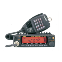
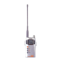
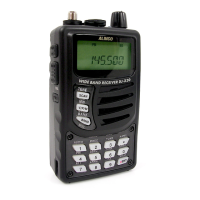
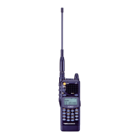
DR-135 / DR-235 / DR-435
Service Manual
CONTENTS
SPECIFICATIONS
GENERAL ........................................................................................ 2
TRANSMITTER ................................................................................ 2
RECEIVER ....................................................................................... 2
CIRCUIT DESCRIPTION DR-135
1) Receiver System (DR-135) ........................................................... 3, 4
2) Transmitter System (DR-135) ....................................................... 4, 5
3) PLL Synthesizer Circuit (DR-135) ................................................. 5, 6
4) Receiver System (DR-235) ........................................................... 6, 7
5) Transmitter System (DR-235) ....................................................... 7, 8
6) PLL Synthesizer Circuit (DR-235) ................................................. 8, 9
7) Receiver System (DR-435) ......................................................... 9, 10
8) Transmitter System (DR-435) ......................................................... 10
9) PLL Synthesizer Circuit (DR-435) ................................................... 11
10) CPU and Peripheral Circuits(DR-135 DR-235 DR-435) ............. 11,12
11) Power Supply Circuit ....................................................................... 13
12) M3826M8269GP (XA0818) ....................................................... 14~16
SEMICONDUCTOR DATA
1) M5218FP (XA0068) ........................................................................ 17
2) NJM7808FA (XA0102) .................................................................... 17
3) TC4S66F (XA0115) ........................................................................ 17
4) TK10930VTL (XA0223) .................................................................. 18
5) BU4052BF (XA0236) ...................................................................... 19
6) TC4W53FU (XA0348) .................................................................... 19
7) M64076GP (XA0352) ..................................................................... 20
8) LA4425A (XA0410) ......................................................................... 21
9) M67746 (XA0412) .......................................................................... 21
10) M68729 (XA0591) .......................................................................... 22
11) M57788 (XA0077A) ........................................................................ 23
12) mPC2710T (XA0449) ..................................................................... 24
13) NJM2902 (XA0596) ........................................................................ 24
14) 24LC32A (XA0604) ........................................................................ 25
15) S-80845ALMP-EA9-T2 (XA0620) ................................................... 25
16) L88MS05TLL (XA0675) .................................................................. 25
17) AN8010M (XA0119) ....................................................................... 26
18) TK10489M (XA0314) ...................................................................... 26
19) Transistor, Diode, and LED Ontline Drawings .................................. 27
20) LCD Connection (TTR3626UPFDHN) ........................................... 28
EXPLODED VIEW
1) Top and Front View ......................................................................... 29
2) Bottom View .................................................................................... 30
3) LCD Assembly................................................................................ 31
PARTS LIST
CPU ..........................................................................................32, 33
Main Unit(DR-135) .................................................................... 33~36
Main Unit(DR-235) .................................................................... 36~39
VCO Unit(DR-235) ......................................................................... 39
Main Unit(DR-435) .......................................................................... 42
VCO Unit(DR-435) ......................................................................... 42
Mechanical Parts ............................................................................ 43
Packing Parts ................................................................................. 43
ACCESSORIES.............................................................................. 43
ACCESSORIES(SCREW SET) ...................................................... 43
TNC(EJ41U) .................................................................................. 44
TNC (EJ41U) Packing Parts ........................................................... 45
DR-135 ADJUSTMENT
1) Adjustment Spot ............................................................................ 46
2) VCO and RX Adjustment Specification ........................................... 47
3) Tx Adjustment Specification ............................................................ 47
4) Rx Test Specification ....................................................................... 48
5) Tx Test Specification ....................................................................... 49
DR-235 ADJUSTMENT
1) Adjustment Spot ............................................................................ 50
2) VCO and RX Adjustment Specification ........................................... 51
3) Tx Adjustment Specification ............................................................ 51
4) Rx Test Specification ....................................................................... 52
5) Tx Test Specification ....................................................................... 53
DR-435 ADJUSTMENT
1) Adjustment Spot ............................................................................ 54
2) VCO and RX Adjustment Specification ........................................... 55
3) Tx Adjustment Specification ............................................................ 55
4) Rx Test Specification ....................................................................... 56
5) Tx Test Specification ....................................................................... 57
PC BOARD VIEW
1) CPU Unit Side A ............................................................................. 58
2) CPU Unit Side B ............................................................................. 58
3) Main Unit Side A DR-135 (UP 0400B) ............................................. 59
4) Main Unit Side B DR-135 (UP 0400B) ............................................. 59
5) Main Unit Side A DR-235 (UP 0414) ............................................... 60
6) Main Unit Side B DR-235 (UP 0414) ............................................... 60
7) Main Unit Side A DR-435 (UP 0415) ............................................... 61
8) Main Unit Side B DR-435 (UP 0415) ............................................... 61
9) Tnc Unit Side A (UP 0402) (DR-135TP only) .................................. 62
10) Tnc Unit Side B (UP 0402) (DR-135TP only) .................................. 62
SCHEMATIC DIAGRAM
1) CPU Unit DR-135 / DR-235 / DR-435 ............................................. 63
2) Main Unit DR-135 ........................................................................... 64
3) Main Unit DR-235 ........................................................................... 65
4) Main Unit DR-435 ........................................................................... 66
5) TNC Unit (DR-135TP only) ............................................................. 67
BLOCK DIAGRAM
1) DR-135 ........................................................................................... 68
2) DR-235 ........................................................................................... 69
3) DR-435 ........................................................................................... 70
ALINCO,INC.
Downloaded by
RadioAmateur.EU