Do you have a question about the Alinx ZYNQUltraScale+ AXU3EGB and is the answer not in the manual?
| Brand | Alinx |
|---|---|
| Model | ZYNQUltraScale+ AXU3EGB |
| Category | Motherboard |
| Language | English |
Overview of the ACU3EG core board and its purpose.
Detailed description of the Xilinx Zynq UltraScale+ MPSoCs EG chip.
Explains DDR4 SDRAM, its capacity, speed, and pin assignments.
Covers the 256Mbit QSPI FLASH for boot images.
Details the 8GB eMMC FLASH for storage.
Details the clock configuration for PS and PL systems.
Describes the power and configuration LEDs on the core board.
Outlines the core board's power supply design.
Provides physical dimensions of the core board.
Details the pin assignments for inter-board connectors.
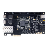
Introduces the carrier board's capabilities and interfaces.
Details the PCIE x1 M.2 interface for SSDs.
Details the DisplayPort output for video display.
Covers the 4 USB 3.0 ports and their specifications.
Explains the dual Gigabit Ethernet ports.
Explains the USB to UART ports for serial communication.
Describes the Micro SD card slot for storage.
Covers the 40-pin expansion headers for connectivity.
Explains the 2 CAN communication interfaces.
Details the two 485 communication interfaces.
Describes the MIPI camera interface.
Covers the JTAG interface for debugging and programming.
Explains the RTC functionality and battery requirements.
Details the EEPROM and temperature sensor.
Describes the power and user LEDs on the carrier board.
Covers the reset and user buttons.
Explains the DIP switch for startup mode configuration.
Outlines the carrier board's power supply schematic.
Details the fan for cooling the ZYNQ chip.
Provides the physical dimensions of the carrier board.