no sound of escaping steam is coming through
the control valve. NEVER ATTEMPT TO OPEN
THE STERILIZER UNTIL THE GAUGE READS
ZERO.
12. With the pressure gauge reading 0 PSI
loosen the wing nuts evenly by turning two
opposite wing nuts counter clockwise. The
wing nuts may still be hot. We recommend
wearing heat resistant gloves to avoid potential
burns. With the wing nuts removed, remove
the cover by turning it counter clockwise.
Remember when removing the cover always tilt
and angle the cover away from yourself or
other people to prevent injury from any
remaining steam in the chamber. PLEASE
NOTE, when the sterilizer is allowed to cool
with the cover tightened to the bottom this
increases the chance that the cover may
become stuck to the bottom.
13. With the cover removed the inner container
may now be removed. In the event that the
inner container remains hot, we recommend
using heat resistant gloves to handle the inner
container. If the sterilizer is not going to be
immediately used again, before storing the unit
all water should be emptied from the unit and
the inside be thoroughly dried. We
recommend pouring the water out of the unit
while it is still warm and leaving the cover off to
let the inside of the chamber dry. The residual
heat will help dry the unit. For storage, place
the cover on the unit and loosely attach the
wing nuts. We recommend leaving the control
valve open (See Fig. 2) to allow air to circulate
through your sterilizer.
14. We have included a sterilization log sheet
that we highly recommend using as best
practice. The sheet will allow the operator to
keep a record of all of the sterilization cycles.
The operator should diligently fill out and keep
the record safe. Additional sheets can be
downloaded for free at our website.
MAINTENANCE
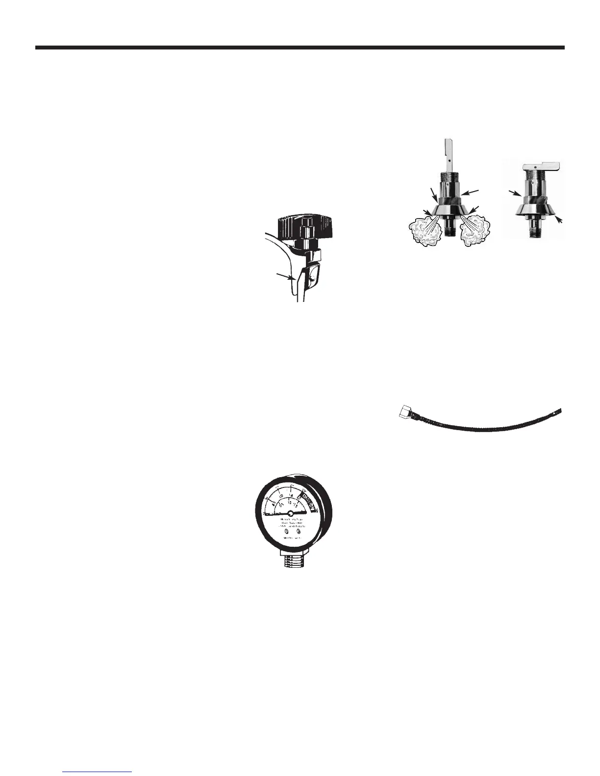
1. Metal-to-Metal seal (See Fig. 1). We
recommend periodically checking the metal-
to-metal seal and lubricating as needed. It is
extremely important to keep the seal lubricated
as failure to do so could cause the cover to
stick potentially making it very difficult to
remove the cover.
2. PRESSURE GAUGE, PART NO. 72S. (See
Fig. 4) Do not immerse your pressure gauge in
water when cleaning the unit. The gauge does
not require any maintenance other than
periodically making sure that the opening of the
gauge on the underside of the cover is open
and free of any foreign matter. DO NOT USE
YOUR UNIT IF THE GAUGE FACE CRACKS,
FILLS WITH STEAM OR DOES NOT RETURN
TO ZERO.
3. CONTROL VALVE, PART NO. 65K (See Fig.
2 & 3). To ensure long life and proper
operation it is important to periodically clean
the control valve thoroughly in hot soapy water.
If distilled water is not used, calcification could
build up and cause the valve to leak. To clean
any built up calcification, put the lever in the
open position and soak the valve in vinegar. Be
sure to clean the control valve in hot soapy
water after soaking in vinegar.
In the event that you are unable to
properly remove any foreign material from your
control valve, we recommend that the control
valve be discarded and replaced with a new
control valve.
4. AIR EXHAUST TUBE, PART NO. 2155 (See
Fig. 5). It is essential that the air exhaust tube
be frequently checked to make sure that air
passes freely through it. We recommend that
you blow air through the exhaust tube at least
once a month to make certain that it is not
plugged with any foreign material. Simply
remove the air exhaust tube from the control
valve on the bottom of the sterilizer cover. The
tube may be cleaned by using a small diameter
wire running through the length of the tube
several times. If you notice any difficulty
cleaning the air exhaust tube or notice any
corrosion on the inside of the passage, we
recommend that you discard the tube and
replace it with a new one.
5. EXCESS PRESSURE RELIEF VALVE, PART
NO. 2050K (See Fig. 6). Your sterilizer is
equipped with a new type of excess pressure
relief valve. It is designed for longer, mainte-
nance free service; however, we recommend
that the valve be replaced every three years in
normal service. The valve is designed to
5
Fig. 4
Pressure Gauge
Fig. 1
Metal-to-metal seal
Apply lubricant here
Open control valve Closed control valve
Fig. 2 Fig. 3
Lever horizontal
o
r closed
L
ever vertical
or open
s
team escape
h
oles
steam escape
holes
valve body
deflector
d
eflector
Fig. 5
 Loading...