2 Publication 1336 IMPACT-5.5ML – May, 1999
1336 IMPACT Quick Start Guide
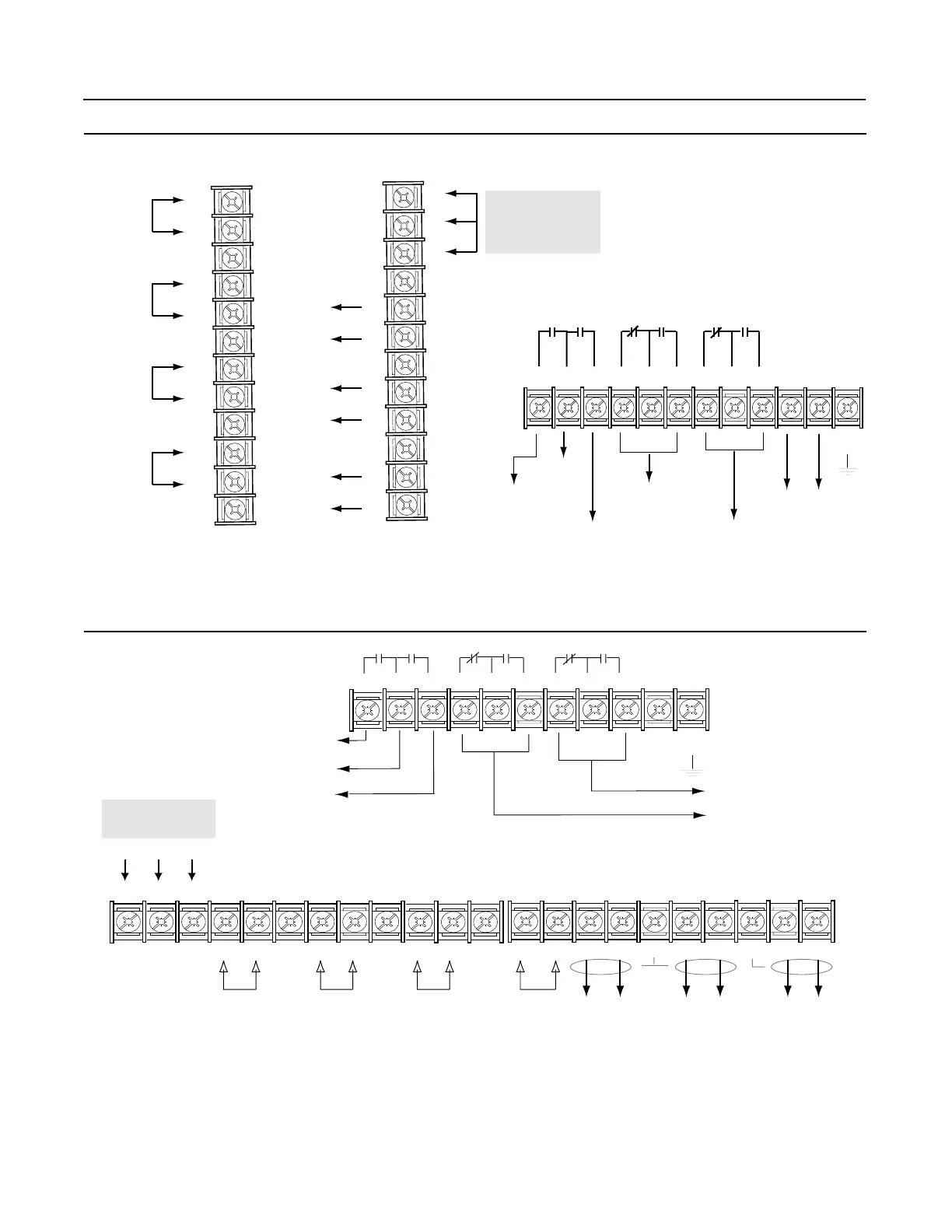
Wiring I/O – A-Frames
Wiring I/O - All Other Frames
J10 (TB10)
+
-
Analog
Input 2
Shield
4 to 20 mA
Pulse
Source
Shield
Shield
Shield
+
-
+
-
+
-
Analog
Input 1
1
2
3
6
9
12
4
5
7
8
10
11
Analog
Output 2
Shield
4 to 20 mA
Shield
Shield
DC Power
Supply*
Analog
Output 1
+
-
+
-
+
-
+10V
Com
-10V
J4 (TB4)
1
2
3
6
9
12
4
5
7
8
10
11
123456789101112
Relay 1
Default: At Speed
Supply
Relay 2
Default: Enable
(Run)
Relay 3
Default: Not Fault
Relay 4
Default: Not Warning
(Alarm)
Voltage
Clearance
TE
* The power supply is for drive
input use only.
J7 (TB7)
123
4
5
6
78 9 10
Relay 1
Default:
At Speed
Supply
Relay 2
Default:
Enable (Run)
Relay 3 Default: Not Fault
Relay 4 Default:
Not Warning (Alarm)
TE
TB11
13 14 15 16 17 18 19 20 21 22
Analog
Input 1
TB10
1 2345 6789
10 11 12
DC Power
Supply
+10V Com -10V
+++++++-------
SH SH SH SH SH
Analog
Input 2
4-20 mA
Input
Pulse
Source
Analog
Output 1
Analog
Output 2
4-20 mA
Output
Voltage
Clearance

 Loading...


