Discrete I/O Modules 25
Publication 1746-IN005A-US-P
Careful wire routing within the enclosure helps cut down electrical noise between
I/O lines. Refer to the SLC 500 Modular Hardware Style Installation and
Operation Manual, publication 1747-6.2, for recommended wiring procedures
for TTL modules.
Cable Length - Limit cable length to 3 meters (10 feet) per point for outputs in
standard environments. Refer to Allen-Bradley Programmable Controller Wiring
and Grounding Guidelines, publication 1770-4.1, for complete information.
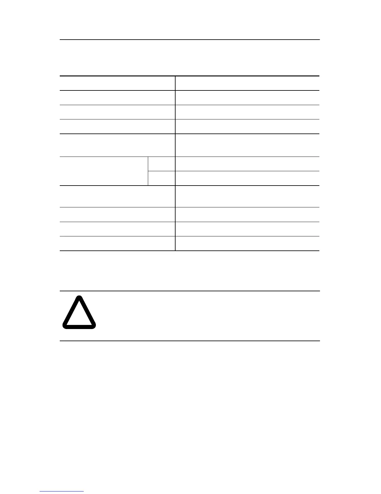
Table 16:Specifications for Output Module 1746-OG16
Specification 1746-OG16
(1)
(1)Removable Terminal Block.
Number of Outputs 16
Points per Common 16
Voltage Category 5V dc TTL Signal Input (sinking)
Operating Voltage
4.5 to 5.5V dc
(2)
50mV peak to peak ripple (max.)
(2)TTL outputs are inverted (0 to 0.4V dc = low voltage = True = ON). Use a NOT instruction
in your ladder program to convert to traditional True = High logic.
Backplane Current
Consumption
5V dc 0.180A
24V dc 0.0A
Signal Delay (max.). Resistive
Load.
on = 0.25 mA
off = 0.50 mA
Off State Leakage (max.) 0.1 mA
Load Current (min.) 0.15 mA
Continuous Current per Point 24 mA
!
ATTENTION: To avoid potential damage to TTL modules,
handle them by the ends of the module, not metallic surfaces.
Electrostatic discharges can damage the module. Care should be
taken to prevent exposure of terminals or components to
electrostatic charges.
Allen-Bradley Spares
 Loading...

