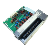
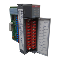
Do you have a question about the Allen-Bradley 1746-NT8 and is the answer not in the manual?
Defines the supported thermocouple and millivolt input ranges for the module's channels.
Crucial safety precautions for handling sensitive electronic components to prevent damage.
Specifies the power consumption of the module for system design and chassis compatibility.
Step-by-step instructions for physically installing and removing the module from the chassis.
General guidelines for connecting input signal cables to the module, including noise considerations.
Detailed steps for preparing cable leads and drain wires for connection to the terminal block.
Details the memory map and addresses for the module's input and output data in the SLC processor.
Explains how to select digital filter frequencies for noise rejection and update time optimization.
Details the factors affecting module update time and provides calculation methods.
A step-by-step guide for configuring the module's input channels via ladder logic or software.
Configures whether a specific channel is active and enabled for scanning by the module.
Sets the type of input device (thermocouple or mV) connected to each channel.
Defines how the input data is expressed in the channel's data word (e.g., engineering units, PID).
Configures the module's response to open-circuit conditions for each channel.
Configures the digital filter for noise rejection and impacts channel update time and resolution.
Detailed explanations of status bits indicating channel conditions, errors, and configuration states.
A basic example demonstrating how to send initial configuration data to the module.
Example for dynamically changing channel configuration to monitor temperature sensors periodically.
Example showing how to use module data as a process variable in the SLC PID instruction.
How to monitor channel status bits for errors and other operational conditions.
A specific ladder logic example demonstrating the monitoring of channel status bits.
Guides users to diagnose module issues by interpreting the status of module and channel LEDs.
A visual guide to systematically diagnose and resolve module issues based on symptoms and LED status.
Essential safety guidelines and precautions for working with electrical equipment and machinery.
Discussion on factors affecting module accuracy, including hardware, software, and temperature variations.
| Manufacturer | Allen-Bradley |
|---|---|
| Product Type | Analog Input Module |
| Series | SLC 500 |
| Input Channels | 8 |
| Backplane Current @ 5VDC | 120 mA |
| Resolution | 16 bits |
| Isolation | 1500 VAC |
| Operating Temperature | 0 to 60 °C |
| Storage Temperature | -40°C to 85°C (-40°F to 185°F) |
| Relative Humidity | 5 to 95% (non-condensing) |
| Input Type | Thermocouple |
| Communication Port | Not applicable |


