Publication 1746-UM022B-EN-P - January 2005
Installing And Wiring Your Module 2-5
Module Installation and
Removal
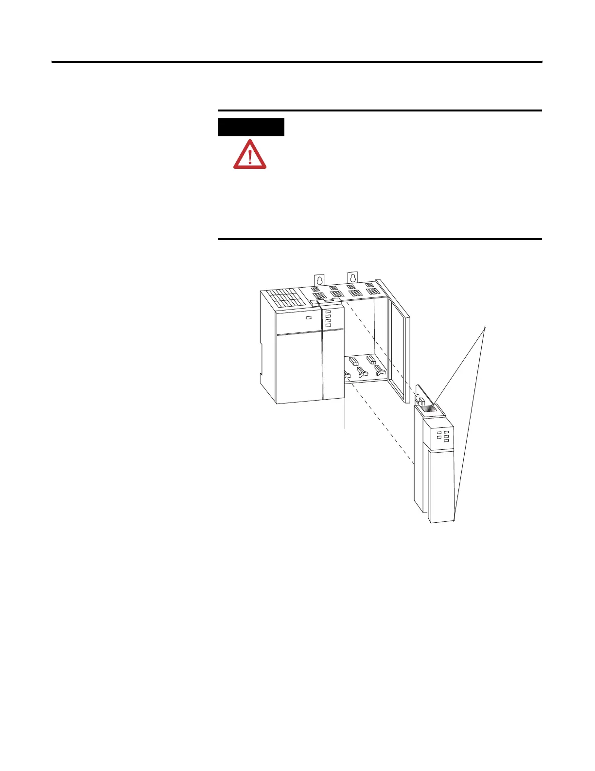
To insert your module into the chassis, follow these steps:
1. Before installing the module, connect the ground wire to TB1.
See the figure on page 2-10.
2. Align the circuit board of your module with the card guides at
the top and bottom of the chassis.
3. Slide your module into the chassis until both top and bottom
retaining clips are secure. Apply firm even pressure on your
module to attach it to its backplane connector. Never force your
module into the slot.
ATTENTION
Possible Equipment Operation
Before installing or removing your module, always
disconnect power from the SLC 500 system and from
any other source to the module (in other words, do
not ’hot swap’ your module), and disconnect any
devices wired to the module.
Failure to observe this precaution can cause
unintended equipment operation and damage.
Card Guide
Top and Bottom
Module Release(s)

 Loading...

